Do you have a question about the Deye SUN-12K-SG01LP1-EU and is the answer not in the manual?
Warning symbols and their meanings regarding electrical hazards, temperature, and proper disposal.
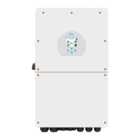
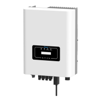
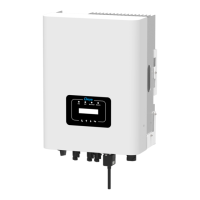
Overview of the hybrid inverter's features, functionality, design, and LCD display capabilities.
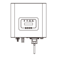
Details the physical dimensions of the hybrid inverter through graphical representations and measurements.
Lists key features like self-consumption, auto-restart, programmable modes, and protection mechanisms.
Illustrates typical system setup with PV, battery, generator, and grid connections for the hybrid inverter.
Lists all components included in the package for the hybrid inverter's installation.
Provides precautions and guidelines for selecting installation site and securely mounting the hybrid inverter.
Details the process for mounting the inverter, including drilling holes, fitting expansion bolts, and securing the unit.
Explains DC over-current protection requirements and provides cable size recommendations for battery connections.
Defines purpose and connections for inverter function ports, including communication and sensor inputs.
Illustrates connecting the battery temperature sensor to the inverter for lead-acid battery systems.
Details procedures for connecting inverter to grid and backup load, including AC breaker and wiring.
Explains necessary DC circuit breaker and cable size recommendations for connecting PV modules to the inverter.
Provides parameters for selecting PV modules, including open circuit voltage and certification standards.
Details steps for connecting PV module wires to inverter input connectors, emphasizing correct polarity.
Illustrates connecting the Current Transformer (CT) for monitoring and zero export functions.
Shows system connection diagram for CHNT meter, including grid input, output, and RS 485 communication.
Emphasizes mandatory grounding procedure for inverter to prevent electric shock and ensure system safety.
Provides guidance on configuring optional Wi-Fi Plug for monitoring inverter performance.
Presents wiring diagrams for grid systems, illustrating configurations for PV, battery, generator, and loads.
Shows typical wiring diagram for integrating diesel generator with hybrid inverter for backup power.
Illustrates wiring diagram for connecting multiple inverters in a single-phase parallel configuration.
Details wiring diagram for connecting inverters in a three-phase parallel system, covering different phase configurations.
Explains procedure for powering hybrid inverter on/off, considering systems with or without batteries.
Describes inverter's operation and display panel, including LED indicators and function buttons for system control.
Details inverter LCD main screen, showing system status, time, energy flow, and power information.
Presents flowchart illustrating navigation and operation flow within the inverter's LCD menu system.
Explains viewing solar, inverter, load, and grid power curves on LCD for daily, monthly, and yearly data.
Details display of solar, load, and grid power curves, including daily, monthly, and yearly generation data.
Overview of System Setup menu, allowing access to various configuration options for the inverter.
Covers basic setup options like time sync, beep settings, display dimming, and factory reset procedures.
Details settings for battery configuration, including mode, capacity, charging, and discharging parameters.
Explains work modes like Selling First, Zero Export, and their configurations for optimal energy management.
Guides users through setting grid parameters, including mode, frequency, voltage, and protection settings.
Details configuration and usage of generator port for power supply and smart load output.
Covers advanced functions like Solar Arc Fault, DRM, Signal Island Mode, and ATS settings for enhanced system control.
Provides inverter ID, firmware versions, and alarm codes for troubleshooting.
Defines pin assignments for RJ45 ports used for BMS communication via RS-485 and CANBus.
Details pin configuration for RS232 port, used for connecting the Wi-Fi datalogger.
Provides physical dimensions and secondary output cable length of the split core current transformer (CT).
| Model | SUN-12K-SG01LP1-EU |
|---|---|
| Type | Hybrid Inverter |
| Rated Output Power | 12kW |
| Max. AC Output Power | 13.2kW |
| Max. DC Input Voltage | 1000 V |
| Max Efficiency | 97.6% |
| MPPT Efficiency | 99.9% |
| Number of MPPT Trackers | 2 |
| Max. Input Current per MPPT | 22 A |
| Power Factor | 0.8 leading to 0.8 lagging |
| THDi | <3% |
| Communication | RS485, Wi-Fi, Ethernet |
| Protection Degree | IP65 |
| Operating Temperature Range | -25°C to 60°C |
| Max. DC Input Power | 15600 W |
| AC Output Voltage | 230 V |
| AC Voltage Range | 180V-280V |
| AC Grid Frequency Range | 50/60 Hz |
| Battery Type | Lithium-ion |
| Battery Voltage Range | 40 V - 60 V |