Do you have a question about the Dhollandia DH-RP.12 and is the answer not in the manual?
| Type | Cantilever lift |
|---|---|
| Lifting Capacity | 1200 kg |
| Platform Width | 2000 mm |
| Platform Length | 1600 mm |
| Power Supply | 24 V DC |
Explains various safety signs including ANSI, DHOLLANDIA, DANGER, WARNING, CAUTION, NOTICE, SAFETY INSTRUCTIONS, and SAFETY ALERT SYMBOL.
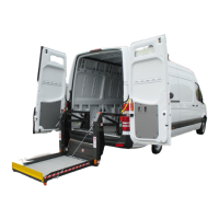
Outlines the manual's purpose, applicability to common vehicles, and manufacturer disclaimers regarding modifications and usage.
Provides details on contacting DHOLLANDIA distributors for support, manual downloads, and product updates.
Emphasizes understanding and applying the Operation Manual and its safety instructions before and during tail lift operation.
Stresses the importance of consulting the General Safety Instructions manual and using proper PPE for safe tail lift installation.
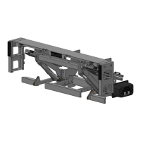
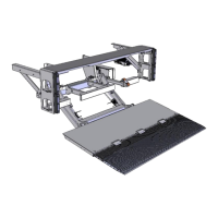
Defines key components of the DH-RP.12 tail lift, including platform sections, cylinders, mounting plates, and hydraulic units.
Explains crucial installation parameters like LARM, VFH, CTH, MFT, MTG, MPG, PD, LOF, and LOP for correct fitment.
Guides on verifying vehicle suitability, chassis strength, body fitting, and preparing the installation site as per OEM and DHOLLANDIA instructions.
Details required installation dimensions, including overhang and vehicle floor height, and the process for verifying compliance.
Covers preparing the vehicle chassis, including floor extension types (Standard/Flush Mount) and necessary chassis modifications.
Provides step-by-step instructions for mounting the extension plate, including alignment, drilling, and securing with bolts or welds.
Details the process of positioning and securing the lift frame, including platform unfolding and using lifting aids for heavy components.
Explains the bolt-on system for mounting plates, alignment procedures, and critical warnings regarding proper torque and welding.
Guides on selecting an appropriate location for the control switch and routing the electrical cable safely to the pump unit.
Lists and defines the functions of each terminal pin on the connection block for wiring the tail lift controls.
Provides the wiring diagram for the gravity down function, showing connections between the control switch, relay, and connection block.
Presents the wiring schematic for the power down function, illustrating connections for the control switch and relay.
Details the general schematic for connecting the tail lift to the vehicle batteries, including the pump motor, solenoid, and fuse.
Outlines steps for pressurizing the hydraulic system, performing functional tests, and checking for leaks before full operation.
Explains how to adjust the platform's pitch and alignment to ensure proper load distribution and safe operation, preventing cargo slippage.
Describes the installation of side steps and dock bumpers, including different set-ups, angles, and welding requirements.
Provides guidelines for lubricating all articulation points using appropriate grease to ensure durability and operational reliability.
Details the final commissioning steps, including function execution, visibility checks, safe-work zones, PDI, and pressure testing.
Explains the application and importance of various safety and instructional decals affixed to the tail lift and vehicle body.
Covers how tail lifts are identified by serial numbers and the information provided on various identification labels.
Compiles warning, mandatory action, and prohibition signs with their meanings for safe operation and installation.
Lists precise torque values for various bolt sizes and strength classes (N.m and lbs-ft) required for secure fastenings.
Provides a comprehensive checklist for inspecting fitting parameters, mechanical parts, electrical systems, hydraulics, and platform functions.
Advises on safe operator positioning, risks of falling/crushing, and recommends installing handgrips for stability.
Details the installation of the 2-button portable control socket, holder, and wiring connections to the control box.
Describes the option of using a resettable circuit breaker for battery connections to protect the system.
Explains how to properly connect the illuminated cab switch for controlling the tail lift's power.
Provides recommendations for minimum cable sections and battery specifications based on electric motor size and usage.
Concludes with notices on preventative maintenance, authorized repairs, genuine parts, and warnings against improper use.