Do you have a question about the Dhollandia DH-R and is the answer not in the manual?
Indicates an imminently hazardous situation.
Indicates a potentially hazardous situation.
Indicates a potentially hazardous situation.
Used for practices not related to physical injury.
General instructions for safe work practices.
Alerts user to potential hazards.
Improper installation can cause damage and injury.
Confirm latest manual version and installer responsibility.
Manufacturer liability disclaimers for modifications, misuse, or installation.
Improper use poses risks of serious injury or death.
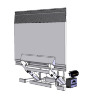
Describes the DH-R* series fold-away liftgates.
Refers to the hydraulic pump unit and controls.
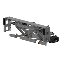
Mounted under chassis, supports platform via arms/cylinders.
Used to mount lift frame to vehicle chassis.
Carries load during operation, consists of main section and flip-over.
Inboard section of foldable platform.
Outboard, foldable section of the platform.
Actuated by cylinders to LIFT/LOWER platform.
Hydraulic cylinders to LIFT/LOWER arms and platform.
Support platform during travel.
Contains motor, pump, oil tank, control valves.
Easy-to-use controls for LIFT/LOWER.
Under run protection device.
Point up to which rated capacity is valid.
Arm assisting platform deployment.
Steel extension mounted to rear sill of vehicle floor.
Steps to help driver climb into vehicle from side.
Rubber buffers on side steps to reduce impact damage.
Steel channels welded under vehicle body.
Steel profiles linking side steps to support channels.
Definitions of power pack components and their functions.
Main junction for connecting controls.
Solenoid for starting electric motor.
Drives the hydraulic pump.
Protects motor from overheating.
Manifold directing hydraulic flow.
Restricts hydraulic flow to reservoir.
Port for connecting pressure gauge.
Maintains safe hydraulic pressure.
Contains hydraulic fluid.
Valve in logic block.
Pumps fluid from reservoir.
Logic block for power down.
Switches hydraulic fluid for power down.
Explains the E2051 connection block layout and function.
Outlines schematic symbols and parts for understanding diagrams.
Schematic of a power down unit when not in operation.
Schematic showing LIFT function activated.
Schematic showing LOWER function activated.
Schematic of a gravity down unit when not in operation.
Schematic showing LIFT function activated.
Schematic showing LOWER function activated.
Procedure for measuring battery voltages and testing.
Testing the functionality of the motor relay.
Verifying the motor's ground connection.
Verifying voltages at the primary toggle switch.
Verifying and adjusting platform leveling.
Troubleshooting auto-tilt issues.
Adjusting platform folding/unfolding issues.
Explains various safety, mandatory, and prohibition signs.
Explains common signs for procedures and functions.
Explains signs related to liftgate operations.
Recommended cable sections for battery and ground cables.
Minimum requirements for batteries and charging systems.
Details the types of oils used in hydraulic systems.
Instructions for running cables through the entry seal.
Steps for connecting battery and ground cables.
How to arrange cables for protection and neatness.
Steps for reassembling the multi-cable entry seal.
Using cable ties to secure cables.
| Brand | Dhollandia |
|---|---|
| Model | DH-R |
| Category | Lifting Systems |
| Language | English |