IV
INSTALLATION/PIPING
The Location of the Techtanium heater.
The Location of the Techtanium heater.
Locate the heater so that there is easy access to the
control, piping, valves, drain and heater for future servicing
and maintenance. The heater is to be kept in an area where
it is not exposed to freezing temperatures.
Also, the heater must be located in an area where a leak
(eg. from the piping or fittings, from any temperature and
relief valve discharge, or from the tank itself), will not
cause personal harm or damage the surrounding area. The
tank should be installed in an area with a floor drain or in a
pan suitable for water heaters.
DHT will not be held liable for any damages caused by
water leakage.
The floor or area where the tank is installed must be
capable of supporting the tank when filled with water.
(Refer to Table at right.)
PIPING
1. General
a. All plumbing must be in accordance
with the requirements of the author-
ity having jurisdiction.
b. Use both thread tape and pipe
dope on all mechanical connections.
c. Zone valve (if used) and circulator
must be sized to provide minimum
flow rate specified in the table to the
right, Flow Specifications. Use 1 inch
nominal copper tubing between boiler
and heat exchanger. See the tables
on Friction Loss. Point of emphasis:
using a zone valve without a full bore
may cause high pressure drop which
will adversely affect performance.
Use extreme care when selecting
zone valve.
d. All piping must be adequately
supported.
e. Allow for thermal expansion.
f. Dielectric Unions (recommended) -
used to electrically isolate the
Techtanium tank from the connected
domestic water piping. This helps to
minimize the possiblity of corrosion
damage.
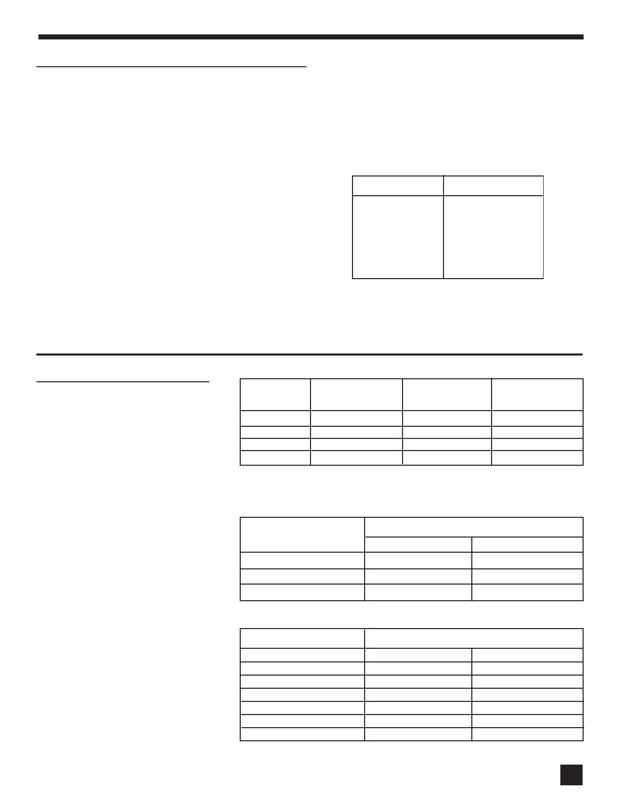
Weight (lbs.) Model
449
576
737
1324
TT-40
TT-55
TT-79
TT-119
TANK WEIGHT WHEN FILLED.
Read the Installation and Operating Instructions manual
thoroughly. Follow recommended piping and wiring diagrams.
Upon completing installation, fill the tank with water. While
filling it leave a hot water faucet open until a steady stream
of water is flowing. Then, shut the faucet and check for any
leaks thoughout the entire system.
FOR YOUR SAFETY: Do not store or use gasoline or other flammable vapors or liquids in the vicinity of this or any other appliance. Controls on
this appliance could ignite vapors causing an explosion.
Flow Specifications
Friction Loss per 100 Feet of Tubing
Friction Loss per 100 Feet of Tubing
(psi)
Model No.
TT-40
TT-55
TT-79
TT-119
Tubing Type
Type K
Type L
Type M
Flow Rate (gpm)
10 gpm 15 gpm
3.1 psi 6.5 psi
2.7 psi 5.7 psi
2.3 psi 4.7 psi
Recommended
Flow Rate
10 GPM
10 GPM
14 GPM
14 GPM
Heat Exchanger
Pressure Drop
(Ft. Hd.)
2.3
2.3
11
11
Domestic Water
Connection Sizes
3/4”
3/4”
1”
1” MPT
Friction Loss Allowance for Copper Fittings
Friction Loss Allowance for Copper Fittings
(feet of straight tubing)
(feet of straight tubing)
Fitting
90º Elbow
45º Elbow
Tee, Run
Tee, Branch
90º Bend
180º Bend
Gate Valve
Wrought
1
1
1/2
3
2
2
–
Cast
4
2
1/2
5
–
–
1
Notes: 1) All fittings are female thread connections except for Domestic Hot and Cold on the
TT-119. 2) TT-119 supplied with adapter to increase from 1" male to 1 1/4" female for
Domestic Hot and Cold.
 Loading...