Do you have a question about the Diamond Audio MSDSP66 and is the answer not in the manual?
Download and install the necessary software for the MSDSP66 processor for desktop access.
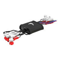
Details on making the correct power connections for the MSDSP66, including RED, BLACK, BLUE, and YELLOW wires.
Guide for making High Level/Low Level input and output connections, ensuring secure device placement.
Contact information for technical assistance with installation.
The MSDSP66 can be used directly with either high-level or low-level audio inputs.
Illustrates input and output connections for OEM and After Market head units.
Section 1 of the software interface, related to hardware connectivity.
Section 2, managing individual channel levels and channel linking.
Section 3, configuring HP/LP type, frequency, and slope settings.
Section 4, displaying the graphic equalizer interface.
Section 5, adjusting Q and gain for equalization.
Section 6, setting time alignment parameters for audio channels.
Utilize the IO Config Screen to map inputs and outputs for the processor.
Configure up to 6 channels of inputs to drive all outputs.
Options to save settings to a PC or load settings to the DSP.
The MSDSP66 is a versatile 6-in 6-out digital signal processor designed to enhance and customize your audio system. This device acts as a central hub for managing audio signals, offering extensive control over various aspects of sound processing. Its primary function is to take multiple audio inputs, process them digitally, and then output them to your amplifiers and speakers, allowing for precise tuning and optimization of your sound stage.
The core function of the MSDSP66 revolves around its ability to process audio signals with high fidelity and flexibility. It supports both high-level and low-level inputs, making it compatible with a wide range of OEM (Original Equipment Manufacturer) and aftermarket head units. This adaptability ensures that whether you're integrating it into a factory system or a custom setup, the MSDSP66 can seamlessly fit into your audio chain.
At the heart of its processing capabilities is a comprehensive software suite that provides an intuitive interface for detailed audio adjustments. This software, which needs to be downloaded and installed on a PC, allows users to connect to the MSDSP66 via a USB connection. Once connected, you gain access to a plethora of controls, including channel level adjustments, crossover settings, a graphic equalizer, and time alignment features.
The channel level control allows you to individually manage the output volume for each of the six channels, ensuring balanced sound across your system. A "channel link" feature simplifies this process by allowing you to group channels and adjust them simultaneously.
The crossover control section is crucial for directing specific frequency ranges to appropriate speakers. Here, you can define the high-pass (HP) and low-pass (LP) filter types, frequencies, and slopes. This ensures that your tweeters receive only high frequencies, your mid-range speakers handle mid-range frequencies, and your subwoofers are fed with low frequencies, preventing damage to speakers and optimizing sound clarity.
A powerful graphic equalizer screen provides granular control over the frequency response of your audio. You can adjust the gain for various frequency bands, allowing you to boost or cut specific frequencies to compensate for acoustic imperfections in your vehicle or to tailor the sound to your personal preference. The "Q adjustment" feature within the EQ control allows you to fine-tune the bandwidth of each frequency band, providing even greater precision in shaping the sound.
Time alignment is another critical feature for achieving an optimal sound stage. This function allows you to delay the audio signal to individual channels, ensuring that sound from all speakers arrives at the listening position at the same time. This creates a more coherent and immersive listening experience, making it feel as if the sound is originating from a single, central point.
The MSDSP66 also includes an "IO Config" screen within its software, which is essential for mapping your inputs and outputs. This feature allows you to define which input channels feed which output channels, offering immense flexibility in system design. For instance, you can use as few as two input channels to drive all six output channels, making it possible to expand a basic stereo signal into a multi-channel setup.
Setting up the MSDSP66 involves a straightforward process, beginning with the installation of its dedicated software. Once the software is on your desktop, connecting the device to your PC via USB enables full control.
Power connections are clearly defined:
The device features status indicators that provide visual feedback on its operational state, including power, Bluetooth pairing, and input sensitivity. Input sensitivity controls (MIN/MAX) allow you to match the output level of your head unit to the input sensitivity of the MSDSP66, preventing signal clipping and ensuring optimal signal-to-noise ratio.
Bluetooth pairing functionality enables wireless connection to the device, potentially for streaming audio or for software control from a mobile device, though the primary control interface is via PC USB.
The physical connections for inputs and outputs are designed for ease of use. The high/low input harness accommodates signals from various sources, while the low-level output harness provides clean, processed signals to your amplifiers. Diagrams illustrate how to connect the MSDSP66 to both OEM and aftermarket head units, demonstrating its adaptability to different system architectures. For OEM head units, the device typically accepts speaker-level inputs, converting them into a clean, low-level signal for processing. For aftermarket head units, it can accept either speaker-level or low-level (RCA) inputs, depending on the head unit's outputs.
The software also includes features for saving and loading presets. You can save your meticulously crafted audio settings as PC presets, allowing you to recall them later or transfer them to another MSDSP66 unit. Conversely, you can load existing presets onto the DSP, making it easy to switch between different sound profiles or to quickly apply a known good configuration. An "Upgrade" option within the software suggests the possibility of firmware updates, ensuring the device remains current with the latest features and bug fixes.
While the MSDSP66 is designed for robust performance, proper installation is key to its longevity and optimal operation. Securing the device free of any obstructions is crucial for adequate ventilation and to prevent physical damage. The quick start guide emphasizes making input and output connections properly, which includes ensuring secure connections to prevent signal loss or interference.
The software's ability to save and load configurations acts as a maintenance feature, allowing users to back up their settings. This means that in the event of a system reset or if the device needs to be replaced, your custom audio profiles can be easily restored without having to reconfigure everything from scratch.
The remote output with a delayed turn-off is a subtle but important maintenance feature. By preventing abrupt power cuts to connected amplifiers, it helps to protect them from potential damage caused by sudden voltage spikes or drops, thereby extending their lifespan.
The availability of tech support (213-212-3182) is a direct maintenance feature, providing users with a direct line to assistance for installation queries or troubleshooting. This ensures that users can get help when needed, minimizing downtime and maximizing the enjoyment of their audio system.
In summary, the MSDSP66 is a powerful and flexible digital signal processor that offers extensive control over your vehicle's audio environment. Its comprehensive software, adaptable input/output configurations, and user-friendly features make it an invaluable tool for anyone looking to achieve superior sound quality and a perfectly tuned audio experience.
| Channels | 6 |
|---|---|
| Maximum Output Voltage | 8V RMS |
| Signal-to-Noise Ratio | >100dB |
| Channel Separation | >70dB |
| Remote Output Voltage | 12V |
| Output Impedance | 100 Ω |
| THD+N @ 1kHz | <0.01% |
| Operating Voltage | 9 V - 16 V DC |
| Power Consumption | 0.5A |
| Total Harmonic Distortion | <0.01% |