EasyManua.ls Logo

Diamond SX-600 User Manual

Diamond SX-600
2 pages
To Next Page IconTo Next Page
Page #1 background imageLoading...
Page #1 background image
INSTALLATION
To install
the SX-200/400
or SX-600/1000
simply connect coaxial cable
directed
to the antenna connector
marked
"ANT",and
The
cable
coming from
the transmitter
or
from
the linear amplifier to
the
connector marked
"TX"
SX-200/400
or SX-600/1000
is ready
to
operate.
POWER
MEASUREMENTS
I
Select the
RANGE
(3)
switch on the end-scale
position
value
as
to the power
of
the unit
2 Select the FUNCTION
(4)
switch in the
power position
3
Select the
POWER
switch the FWD position
to
measure the
direct
power(from
the radio
to
antenna)
or
REF
position
to measure
the reflected
power(from
antenna to the radio)
4
Select
the
power
value can be read on the corresponding scale.
SWR MEASUREMENTS
I
Select
the RANGE
(3)
switch on the end-scale
position
value as to the
power
of the unit.
2
Select the FUNCTION
(4)
switch
in the
CAL
position
.
3 Let the
radio
transmit
and adjust the instrument by turning the CAL knob,
position
the end-scale index
in
the
CAL
position.
4
Select the FUNCTION
(4)
switch
in the
SWR
position
5 Read the SWR value in
the
above
scale.
FrGs
(FOR
SX-200 OR SX-400) FIG6
(FOR
SX-600 or SX-1000)
TO ANT
TO RADIO TO ANT TO RADIO TO RADIO TO ANT
(f
.8-r60MHZ) SX-600
(r40-s25
MHZ\
(r.8-r
60M HZ)OR( | 10-s2s M HZ)
sx-r000(430-1300M
HZ)
REMARK: SWR VS.
REFLECT POWER
/
rrwo
+y'
Prev
SWR
(STANDING
WAVE RATIO):
i
pr-d
tF';
SPECIFICATION
FREQUENCE
RANCE:
MHZ
(SX-400,SX-600),
SWR t.0 l.l 1.2 1.5 2.0
tq
3.0
Prev% 0 0.22 0.8
4
n.l 8.4
25.1
POWER
MEASURE
t5%
,2OW
RANGE t7.5o/",
200w RANGE
+l0o/o
,400W
RANGE t12.5'/o

Other manuals for Diamond SX-600

Question and Answer IconNeed help?

Do you have a question about the Diamond SX-600 and is the answer not in the manual?

Diamond SX-600 Specifications

General IconGeneral
Input/Output Impedance50 ohms
ConnectorsSO-239
FunctionsSWR and Power Meter
Power Range5W/20W/200W
Dimensions155W x 63H x 103D mm

Summary

Installation Guide

Power Measurement Procedures

Selecting Power Range and Function

Instructions on selecting the appropriate range and function switches for power measurement.

Measuring Forward and Reflected Power

Steps to set the power switch for FWD or REF and read the measured value.

SWR Measurement Procedures

Calibrating for SWR Measurement

Steps for setting the range, function to CAL, and adjusting the CAL knob.

Reading SWR Value

Instructions on selecting the FUNCTION switch to SWR and reading the value.

SWR vs. Reflected Power Remark

SWR Calculation and Table

Formula for SWR and a table showing SWR values against reflected power percentages.

Technical Specifications

Frequency and Power Ranges

Details on supported frequency ranges and power measurement ranges.

Precision and Impedance

Specifications for precision, SWR limits, impedance, and input loss.

Physical Dimensions and Weight

Information on the unit's dimensions and weight for different models.

Operating Instructions

Meter Functionality and Power

Describes the meter's efficiency, insertion type, and operation with/without external power.

Description of Controls

Front Panel Controls and Indicators

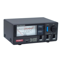
Lists and describes front panel controls like meters, switches, and connectors.

Rear/Side Panel Connectors and Indicators

Details rear panel connectors for antenna, TX, and power, plus LED indicators.

Related product manuals