Do you have a question about the Diamond X300A and is the answer not in the manual?
Features C-Load structure with Liner Phase Shifter for high performance, high power rating, low VSWR, and broad band coverage.
Utilizes direct joint structure with FRP outer-shells and a waterproof gasket for durability and weather resistance.
Professional quality rugged structure ensures maximum wind resistance and superior waterproofing for reliable performance.
Supports simultaneous operation of 2m and 70cm bands when using an optional antenna duplexer.
Incorporates a DC ground structure to protect radio equipment from high voltage caused by lightning.
Covers 144-148 MHz for 2m band and 435-450 MHz for 70cm band.
Provides 6.5 dB gain for the 2m band and 9.0 dB gain for the 70cm band.
Accepts a maximum power input of 200 Watts.
Features 50 Ohms impedance and a VSWR of less than 1.5:1.
Rated for 50m/sec (112 MPH) wind resistance and accepts mast diameters of 30-62mm.
Measures 2.9m in length, weighs 1.9 kg, and uses a UHF Female connector.
Comes with a 1-Year warranty against defects in material or workmanship.
Graphical representation of VSWR across frequency bands for 2m and 70cm.
Diagram illustrating the assembly of the antenna components, including element brackets and radial elements.
Instructions for connecting upper and lower elements, outer shells, and radial elements.
Details on attaching mast brackets, connecting the coaxial cable, and mounting the antenna on a mast.
Advisories regarding electric power lines, weather conditions, and the need for assistance during installation.
Guidance on what to do if the antenna starts to fall or touches an electric power line.
Instructions for handling situations where a person or animal may be in contact with a live power line.
Factors to consider for antenna location, including propagation, obstacles, support, and safety from power lines.
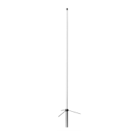
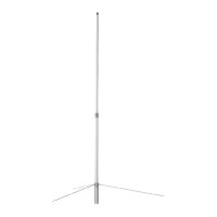
The Diamond X300A is a dual-band, high-performance base station antenna designed for 2m (VHF) and 70cm (UHF) amateur radio bands. It is engineered to provide reliable communication with a focus on durability, weather resistance, and ease of installation.
The primary function of the X300A is to transmit and receive radio signals on the 144-148 MHz (2m) and 435-450 MHz (70cm) frequency bands. It utilizes a high-performance C-Load structure with Liner Phase Shifter technology, which contributes to its high power rating, low VSWR (Voltage Standing Wave Ratio), and broad band coverage. This design ensures efficient signal transfer and reception across both operating bands. The antenna features a DC ground structure, which is a crucial safety feature. This design helps to protect connected radio equipment from high voltage surges caused by lightning strikes, diverting the electrical energy safely to ground. This makes the antenna suitable for long-term outdoor installation where lightning exposure is a concern.