EN
12
S3
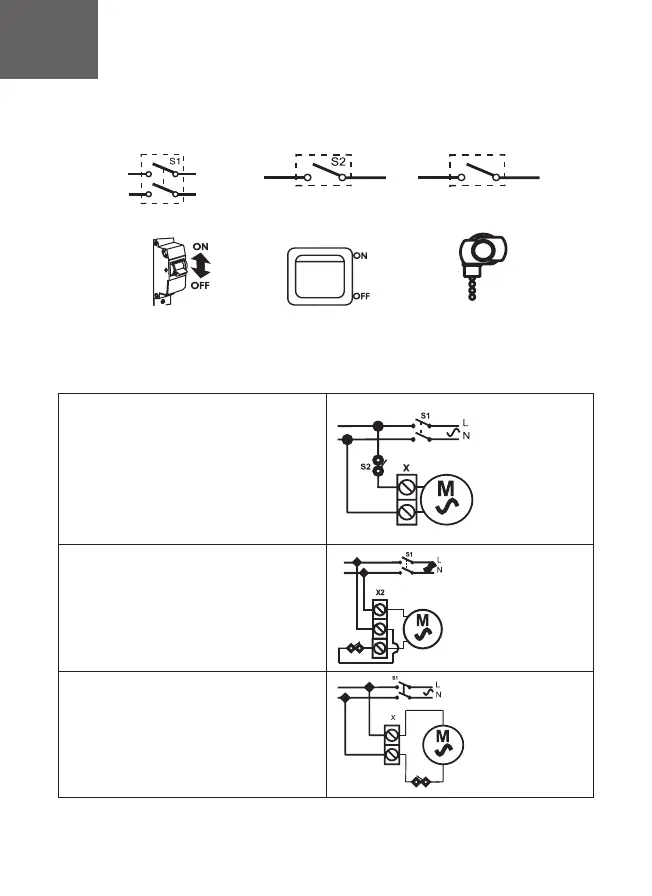
Legend of circuit breaker S1
on the scheme
Сircuit breaker S1
External switch S2
Built-in switch S3 (pull chain
switch)
Legend of external switch
S2 on the scheme
Legend of built-in switch S3 on
the scheme
Schematic diagrams of DICITI fan`s connection
Scheme 1
of fan connectuion (base model)
X- terminal block, 2 pairs
Scheme 2
of fan connection, equipped with - 02 option(pull-
chain switch).
X2- terminal block, 3 pairs
S3
Scheme 3 (for SLIM model)
of fan connection, equipped with - 02 option(pull-
chain switch)
X- terminal block, 2 pairs
S3
220-240V
220-240V
220-240V
PARUS (Pic. 4)
• remove the decorative front panel and terminal block
cover
• hold the power wire through the cable hole 1 in the case
• strip the insulation on 5-7 mm from the wire end
• insert wires into terminal box X and press them by tap
screw
• fix the wires by means of cable clamp 2
•install the cover of terminal block and front panel by easy
pressure
PARUS -02 (Pic. 5)
• remove the decorative front panel and terminal block
cover
• hold the power wire through the cable hole 1 in the
case
• strip the insulation on 5-7 mm from the wire end
• insert wires into terminal box X and press them by tap
screw
• fix the wires by means of cable clamp 2
• install the cover of terminal block and front panel by
easy pressure
AURA/SILENT (pic. 1)/SLIM (pic.2-3)
• remove the decorative front panel
• hold the power wire through the cable
hole 1 in the case
• strip the insulation on 5-7 mm from the
wire end
• insert wires into terminal box X and press
them by tap screw
• fix the wires by means of cable clamp 2
• combine clamps of the decorative panel
with grooves in the case
• fix the panel with screw
 Loading...