EN
13
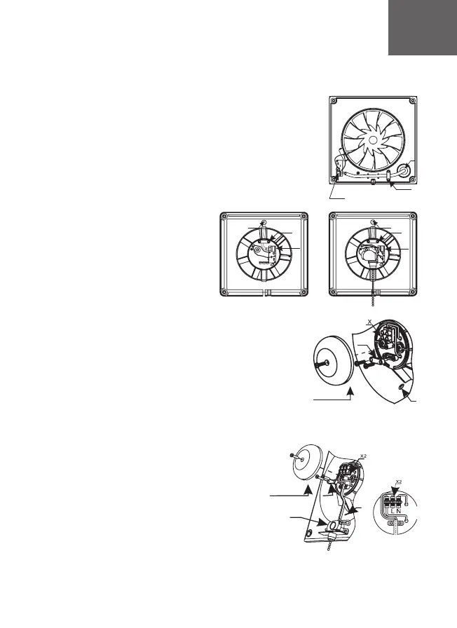
PARUS (Pic. 4)
• remove the decorative front panel and terminal block
cover
• hold the power wire through the cable hole 1 in the case
• strip the insulation on 5-7 mm from the wire end
• insert wires into terminal box X and press them by tap
screw
• fix the wires by means of cable clamp 2
•install the cover of terminal block and front panel by easy
pressure
PARUS -02 (Pic. 5)
• remove the decorative front panel and terminal block
cover
• hold the power wire through the cable hole 1 in the
case
• strip the insulation on 5-7 mm from the wire end
• insert wires into terminal box X and press them by tap
screw
• fix the wires by means of cable clamp 2
• install the cover of terminal block and front panel by
easy pressure
Pic.4 PARUS, PRO
Pic.5 PARUS -02
Wiring diagram connection of DICITI fans to the network
Connection of fan to the network shown in pic. 1-8
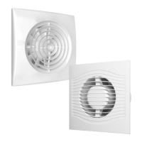
AURA/SILENT (pic. 1)/SLIM (pic.2-3)
• remove the decorative front panel
• hold the power wire through the cable
hole 1 in the case
• strip the insulation on 5-7 mm from the
wire end
• insert wires into terminal box X and press
them by tap screw
• fix the wires by means of cable clamp 2
• combine clamps of the decorative panel
with grooves in the case
• fix the panel with screw
2
3
1
1
2
X
1
2
X
Pic.1 AURA
/SILENT
Pic.2 SLIM Pic.3 SLIM -02
2
1
S
3
cover
of terminal
block
1
2
cover
of terminal block
 Loading...