Do you have a question about the Dicon 650M and is the answer not in the manual?
Essential guidance for electrical installation, circuit requirements, and interconnecting alarms according to standards.
Step-by-step instructions for wiring, including new cable colour coding and connection methods.
Recommendations for optimal placement of smoke and heat alarms and areas to avoid for effective detection.
Details on alarm features, operating lights, pause function, and essential fire safety advice for users.
Instructions for regular cleaning and testing of alarms to ensure optimal performance.
Procedures for changing batteries in various MBX and other model types.
Guidance on identifying and resolving common alarm issues and managing false alarms.
Information regarding the radioactive content of ionization alarms and proper disposal methods.
Details on the product warranty and conditions for service.
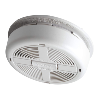
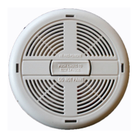
This document describes a range of Dicon Mains Powered Smoke and Heat Alarms, including Photoelectric Smoke Alarms (650M, 650MC, 650MRB, 650MRL, 650MBX), Ionization Smoke Alarms (670M, 670MC, 670MRB, 670MRL, 670MBX, 370MBX), and Heat Alarms (680M, 680MC, 680MRL, 680MRB, 680MBX). These are 220-240VAC Class II apparatus designed for mains power. The manual emphasizes the importance of reading and retaining the owner's manual, especially when installing the alarm for others, in which case a copy should be left with the end user.
Before initial use, specific checks are required. For 370MBX, 650MBX, 670MBX, and 680MBX models, users must ensure the battery is fitted correctly and that the alarm is not beeping. A crucial step is to test the alarm before switching on the electricity supply. For all alarm types, users should verify that the green light (located behind the front grille) is on and that the red light flashes approximately every 45 seconds. When dealing with linked alarms, it's essential to check that all interconnected alarms activate within 10 seconds during a test.
The manual highlights several important notes regarding alarm behavior. The 370MBX model will beep for 10 minutes if its pause button has been pressed. Alarms equipped with rechargeable batteries or capacitor backup may beep for up to 2 hours while these components are charging. It is strongly advised to leave a copy of the handbook with the user and ensure they understand how to use and maintain the alarm.
Installation must be performed by a qualified electrician in accordance with BS7671. A permanent connection to the building's fixed wiring should be made in a suitable junction box. The alarm must be protected from dripping or splashing. To prevent contamination, especially in new builds, the alarm should be connected as late as possible in the installation process. The dust cover must be removed before applying power. Detailed guidance on alarm siting is provided in section C of the handbook.
A critical point is that the circuit powering the alarm must be a 24-hour voltage circuit that cannot be turned off by a switch. BS5839 Part 6 specifies that for mains-powered alarms with an integral standby supply (Grade D), the mains electricity supply should either be an independent circuit at the dwelling's main circuit board (with no other electrical equipment connected, except a dedicated monitoring device for supply failure) or a separately electrically protected, regularly used local lighting circuit. For mains-powered alarms without standby supply (Grade E), only an independent circuit as described above is permissible. If an RCD is used for protection, it must operate independently of any RCD protection for circuits supplying sockets or portable equipment. All interconnected alarms must be installed on a single final circuit.
The maximum interconnect wiring length is 250 meters, and a maximum of 12 alarms can be interconnected. Dicon smoke alarms should not be connected to models from other manufacturers. Alarm locations must comply with applicable building codes and the advice in section C.
The manual provides important information regarding electrical cable colour coding changes. Old colours (Red, Yellow, Blue, Black) correspond to new harmonized colours (Brown, Black, Grey, Blue) for L1, L2, L3, and Neutral, respectively. These new colours have been in use since March 31, 2004, and became mandatory after March 31, 2006. When selecting cable for interlinked smoke alarms, the interlink wire should be treated as live.
Two installation methods are illustrated: one suitable for plasterboard ceilings with void access and a junction box, and another for concrete or similar ceilings where access is insufficient or surface wiring is necessary. Users must connect the brown wire to the brown (live) in the house wiring and the blue wire to the blue (neutral). No connection should be made to the mains electricity supply earth terminal; instead, the house wiring earth should be terminated in a spare connector.
For multiple alarm installations, a "three core and earth" style cable should be used between all interconnected alarms. The third core of this cable connects to the white wire from the smoke alarm. The earth wire must not be used for the interconnect line; it must be treated as live, meaning it should be insulated and sheathed. If an alarm is not to be interconnected, the unused wires should be capped. The baseplate is removed from the alarm by twisting it anti-clockwise about 12mm, and the locking pin is detached.
For optimal protection, smoke alarms should be installed in every room, excluding those listed in the 'Locations to Avoid' section. Heat alarms are recommended for kitchens, boiler rooms, laundry rooms, garages, and similar areas where smoke alarms would be unsuitable. All alarms must be interconnected.
In circulation areas, smoke alarms should be no more than 7.5m from the farthest wall, from any room door where a fire might start, from the next smoke alarm, and no more than 3m from a bed. When heat alarms are installed in a room, they should be no more than 5.3m from the farthest wall, from any room door where a fire might start, and from the next heat or smoke alarm.
The ideal location for an alarm, given the unpredictability of fire sources, is the center of a room or hallway. If wall-mounted, the detection element should be 150mm to 300mm (6 to 12 inches) below the ceiling, with the bottom of the alarm above doors and other openings. Heat alarms should not be wall-mounted. In rooms with sloped, peaked, or gabled ceilings, smoke alarms should be installed 900mm (3 feet) from the highest point to avoid "dead air" that could delay smoke detection. Closed doors and other obstructions can impede smoke and heat, so sufficient alarms should be installed to compensate. Local fire brigades or insurance companies can offer further advice, as can BS5839 Part 6 and guidance from the Department of Transport, Local Government and the Regions (DTLR). Research indicates that additional alarms significantly increase warning time, so following these guidelines for maximum protection is strongly recommended.
The manual provides diagrams for recommended alarm placement in single-storey (one and two sleeping areas) and two-storey dwellings, indicating smoke alarms for limited protection, additional smoke alarms for better coverage, and heat alarms. These alarms are primarily for single-family occupancy private dwellings; for other applications, manufacturer advice should be sought.
Alarms should not be located in areas with turbulent air from fans, heaters, doors, or windows. High humidity areas like bathrooms or shower rooms, or where temperatures exceed 39°C (100°F) or fall below 5°C (40°F), should be avoided. The peak of an 'A' frame ceiling can accumulate "dead air" that prevents early detection. Alarms should not be less than 300mm (12 inches) from a wall when ceiling-mounted. Insect-infested areas can affect performance. Poorly ventilated kitchens or garages (for smoke alarms) can trigger nuisance alarms due to combustion particles from cooking or car exhaust. Very dusty or dirty areas can impair performance. Alarms should not be within 300mm (12 inches) of a light fitting or room corners. Locations that make routine testing or maintenance hazardous (e.g., over a stairwell) should be avoided. Poorly insulated walls or ceilings, and near objects like ceiling decorations that impede smoke or heat, are also unsuitable. Alarms should not be within 1500mm (5 feet) of a fluorescent light fitting, and wiring should be at least 1000mm (39 inches) away from these fittings. Alarms should not be installed on circuits containing fluorescent light fittings or dimmer switches.
Smoke and heat alarms, when properly installed and maintained, are crucial components of a home fire safety program. Users should review fire hazards and eliminate dangerous conditions where possible. A well-prepared and practiced escape plan is vital in case of fire. Local fire brigades can provide advice. Users should familiarize themselves with the alarm signal, test doors for warmth before opening them (if warm, find another escape route), and prioritize evacuating all occupants over collecting possessions. The mantra is "GET OUT, STAY OUT, GET THE FIRE BRIGADE OUT!" After escaping, everyone should meet at a designated meeting place. If trapped inside, stay close to the floor, cover your mouth with cloth, and conserve breath while crawling to safety. All windows and doors should remain closed except for escape purposes. Users should prepare and practice an escape plan, including drawing a floor plan and conducting regular fire drills.
To ensure efficient operation, the unit should be vacuumed every six months. First, turn off the mains electricity supply. Use a soft brush attachment to vacuum through the vents, ensuring the nozzle does not touch the unit. Remember to switch the power back on after cleaning.
Test the alarm once a week by checking that the green light is on and the red light flashes approximately every 45 seconds (lights are behind the front grille). Then, press and hold the test button until the alarm sounds. Note that pressing the test button on 670 series alarms also activates the pause mode.
For MBX models, the battery should be changed when the alarm beeps every 45 seconds.
370MBX Models Only: Turn off the mains electricity supply. Remove the locking pin by inserting a small screwdriver into the square hole at the top of the battery drawer, applying pressure to push the pin up. The pin will pop out. Open the battery drawer, remove the old battery, and insert the new battery (contacts first, according to markings). Close the drawer and test the alarm using the test button. Refit the locking pin and then turn on the mains electricity supply. Note that the battery drawer cannot be closed if the battery is missing.
All other MBX Models (Excluding 10-year Lithium versions): Turn off the mains electricity supply. Remove the locking key, rotate the alarm approximately 10mm anti-clockwise, and remove the alarm from the ceiling. Unplug the alarm from the mains supply. Remove the screw and prise open the battery compartment door on the back of the alarm. Replace the battery with one of the following: Duracell MN1604, MX1604, Eveready PP3B PP3S, 6LF22 Gold Peak 1604A, 1604S. Close the battery door, refit the screw, and re-assemble the alarm to the ceiling, ensuring the mains plug is securely fitted. Test the alarm using the test button, then turn on the mains electricity supply. Note that the alarm cannot be fitted to the baseplate without a battery installed.
650MBX-10, 670MBX-10, and 680MBX-10: These alarms are fitted with a 9-volt lithium battery. Replace with Ultralife U9VL batteries.
The manual addresses common problems such as the alarm not sounding during a test, the green light being off, the red operating light not flashing, or the alarm emitting intermittent beeps. Suggested solutions include inspecting the wiring, gently vacuuming the alarm, and for MBX models, checking the battery. If these steps do not resolve the issue, users are advised to contact the manufacturer or a qualified electrician. If the alarm is still under guarantee, it should be returned to the distributor for repair.
False alarms can be caused by abnormal air currents or dust. Users are warned not to disconnect the alarm if it is due to a false alarm, as this would disable its protective function. Dust can affect performance, and painting the alarm is discouraged. Other factors like cooking fumes or steam can also trigger false alarms.
Ionization type smoke alarms contain a small amount of radioactive material (Americium 241, typically less than 37 kilobequerels). This represents no health hazard and is rigorously tested.
As a responsible manufacturer, Dicon Safety Products adheres to all regulations and procedures regarding the disposal of ionization type smoke alarms, including changes in European legislation. For the latest information, users can contact Dicon Safety Products (Europe) Ltd.
Dicon Alarms are guaranteed for 5 years from the date of purchase against faulty materials and workmanship under normal use. This guarantee does not cover damage from misuse or accidental damage. The guarantee is in addition to statutory rights. In the event of a problem, users should contact customer service.
| Power Source | 9V Battery |
|---|---|
| Sensor Type | Photoelectric |
| Alarm Sound Level | 85 dB |
| Operating Temperature | 40°F to 100°F (4°C to 38°C) |
| Compliance | UL 217 |