2
2.2 SENSOR MODULE
2.2.1 The Sensor Module measures the System
Pressure, Line Pressure, Air Flow, Humidity, and
Incoming Voltage with its onboard sensors. External
sensors for Low Wat er, High Water, and Water Tem-
perature are wired directly into the sensor board.
2.2.2 The purge valve timing sequence (27 seconds
purge with 3 seconds of dwell) and the cooling fan
control circuits also reside with the Sensor Board.
The fan comes on once the water temperature reaches
90°F otherwise it will be off especially if the optional
Water Chiller Kit (P/N 101961) is installed.
2.3 ALARM/ATS MODULE
2.3.1 This module provides for alarm interfacing as
well as AT S300 connections. (See Appendix A for
additional detail).
2.3.2 Two summary alarm outputs and a 10 alarm
segregation outputs are available for an Alarm
Monitoring system. All outputs are dry contacts
and isolated from one another and may be wired for
open or closed in alarm. The Segregation Alarm is
factory configured for closed in alarm but can be
re-configured for open in alarm by moving two on-
board jumpers. Ter mination is with dis-connectable
terminal blocks for easy connection and removal.
Summary alarm CO#1 may be configured for 540k
Ohm/270k Ohm and 270k Ohm 0 Ohm Alarms.
2.3.3 Male and female D sub 9 position connectors
are provided for AT S300/ATS300PLUS bus cable
termination. This interface is built into the module
so no additional external interfacing is needed. An
on-board jumper is used to configure the last dryer
connected. Addressing is accomplished through
Menu-Setup.
2.3.4 A switch for Manual Dryer operation is pro-
vided to place the Dryer off-line with an ATS 300/
ATS 300PLUS Transfer System and allow mainte-
nance and troubleshooting capability. This switch
function is like the one used on the AT S300 IUC
interface panels.
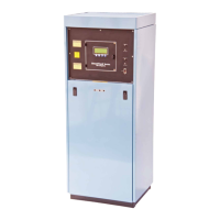
2.4 CABINET FEATURES
2.4.1 The lower front panel of the Dehydrator is
removed by lifting and then turning the two latches.
Each side panel is held by four screws at the rear of
the cabinet. The side panels can be removed when
the screws are loosened. Move the panel sideways
to clear the cabinet and push it forward to remove.
2.4.2 Never place objects on top of the dehydrator. It
will interfere with the air flow of the cooling fan.
2.4.3 The front panel which contains the display
and ON/OFF switch is also the access panel to the
fuses and high voltage components. There is never
a need to open this panel for routine maintenance.
Observe warning labels and always disconnect the
power supply to the dehydrator before opening this
panel.
2.4.4 The cabinet acts as a cooling duct for the
compressors and heat exchangers of the dehydrator.
Excellent cooling is provided when the rear cabinet
air filters are clean and all panels are in place. Do
not operate the dehydrator for long periods with the
panel removed.
- - - NOTE - - -
All machinery must be fitted with means to isolate
it from electrical energy sources. The isolator must
be capable of being locked where an operator is
unable , from any of the points t o w h ich he/she has
access, to check that the energy is still cut off!
An External Surge Protection Device should be
used when operating this device. This Equipment
is suitable for Common or Isolated Bonding and
for Network Telecommunication Facilities and
locations where NEC applies.
2.5 COMPRESSOR
2.5.1 The SmartTech™ Dehydrator has two ST
Watersealed Rotary Air Compressors. These com-
pressors are a higher output capacity over prior
compressor series and features a quick disconnect
vertical manifold for easy removal without the need