IR4420 & ER4420/i/p Installation Guide
6
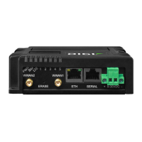
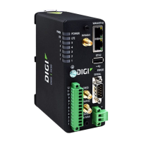
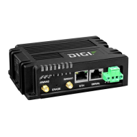
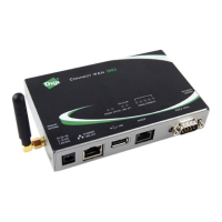
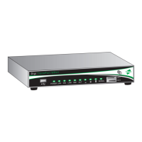
Status Indicators
The status indicators operate as follows:
ON
Illuminates steady red when power is applied.
LAN 0, 1, 2, 3
Illuminate steady when there is a network connection to the
associated LAN port and flash when data is transmitted or
received.
EDGE:
NET, SIM,
DAT
On the ER4420, ER4420i and ER4420p, these indicators operate
as follows:
NET – Illuminates green when an EDGE network has been
detected.
SIM – Illuminates green when a valid SIM card is installed in the
unit.
DAT – Flashes green when data is being transmitted or received.
SIGNAL
The three indicators labelled SIGNAL illuminate to indicate the
GSM signal strength as follows:
None illuminated < -113 dBm (effectively no signal)
1 LED illuminated >= -112 dBm and <= -87dBm (weak)
2 LED’s illuminated >= -86dBm and <= -71dBm (medium)
3 LED’s illuminated >= -70dBm and <= -51dBm (strong)
ISDN:
D, B1, B2
On the IR4420 and ER4420i, these indicators operate as follows:
D – Illuminates green when the unit is connected to an ISDN
network and the D-channel signalling layer is active.
B1 – Illuminates green when ISDN B-channel 1 is active and
flashes when data is being transmitted/received over this
channel.
B2 – Illuminates green when ISDN B-channel 2 is active and
flashes when data is being transmitted/received over this
channel.
PSTN:
OH, CD, DAT
On the ER4420p, these indicators operate as follows:
OH – Illuminates green when the modem has gone off-hook.
CD – Illuminates green when the unit has connected to a remote
modem and asserted the Carrier Detect signal at the serial port.
DAT – flashes green when the unit has connected to a remote
modem and data is being transferred.
IR4420 & ER4420/i/p Installation Guide
7
SERIAL:
0, 1
These indicators operate in one of two software configurable
modes:
Connection Mode: Illuminate steady if a terminal is connected to
the serial port and the DTR signal is on. Flash when data is
transmitted or received.
DTR Mode: Flash when data is transmitted or received only.
SIM Card Sockets
The two sockets at the right side of the front panel are for the GSM SIM card(s) that you
will receive from your service providers. Details of how to insert these correctly are given
in section 2 below.
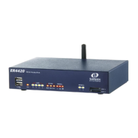
Rear Panel Features
The functions of these connectors are described in the following table:
12V DC
This jack socket is used to connect the unit to the power supply
using 12V DC mains adapter.
LAN 0, 1, 2, 3
The LAN sockets are used to connect the unit to 10/100-BaseT
LANs using the 2-metre STP (Shielded Twisted Pair) cable
supplied or a suitable alternative. These ports are auto-sensing
for speed and wiring (straight-through or cross-over). To comply
with EMC requirements they should not be used with non-STP
cable.
EDGE
This SMA connector is used to fit the dual-band GSM stub aerial
supplied with the unit. A range of alternative antennas are
available for purchase separately.
SERIAL 0, 1
These 25-way D sockets provide synchronous/asynchronous
RS2322 serial ports which may be used to connect the router to
compatible serial devices. The unit is supplied with a suitable 2
metre serial cable. To comply with EMC requirements it should
not be used with a longer cable.
ISDN/PSTN
This socket is used to connect the router to an ISDN or PSTN
line.
Reset Switch
This is located on the underside of the unit near the front. Pressing the switch gently with
the tip of a pen or other suitable implement will generate a hardware reset.