Meter Engineers Handbook for Cellular Communication 12
4.4 Schneider Square D ION8650 Meters
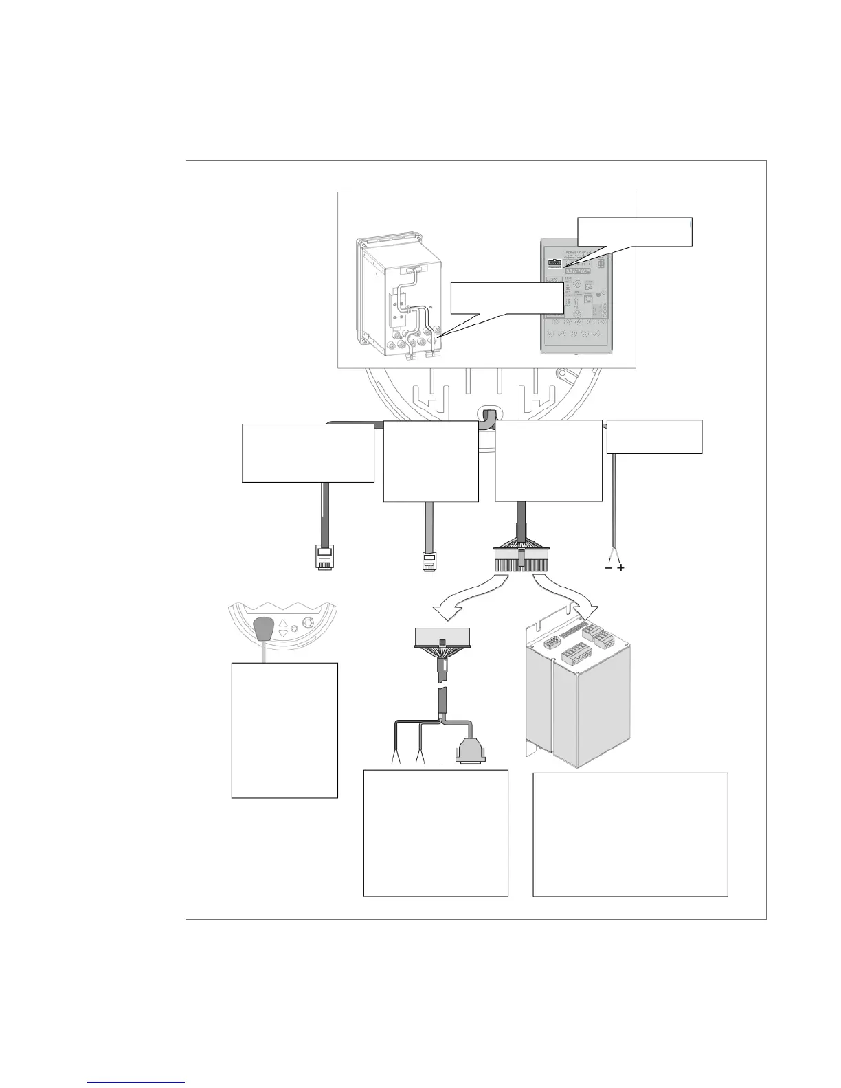
The following illustration shows the connection to the communications card.
PowerLogic ION8650 – Energy and power quality meter User guide. Pg. 84
Ethernet 10/100Base-T:
RJ45 connector.
Modem on
COM2:
RJ11 male
connector.
ANSI Type II
Magnetic Optical
Communications
Coupler on
COM3. This port
is located on the
front panel.
Optical communications
breakout cable for serial
communications.
Ordered separately.
COM1: RS-232 or RS-485.
COM4: RS-485.
Optical I/O Expander for serial
communications (and expanded I/O).
Ordered and shipped separately.
Serial COMs
COM1: RS-232 or RS-485.
COM4: RS-485.
Communications wiring
on breakout panel
Communications wiring
on switchboard
IRIG-B GPS Time
Synchronization.
Back view of ION8650
Serial COMs and
Expanded I/O: Molex
Micro-Fit 24 pin male
connector.
 Loading...