EasyManua.ls Logo

Digigram PCX 924 - Additional Connectors and Switches; Digital and CD Input Connectors; Switch Configurations

Digigram PCX 924
12 pages
Print Icon
To Next Page IconTo Next Page
To Previous Page IconTo Previous Page
Loading...
PCX 924
User’s Manual
9
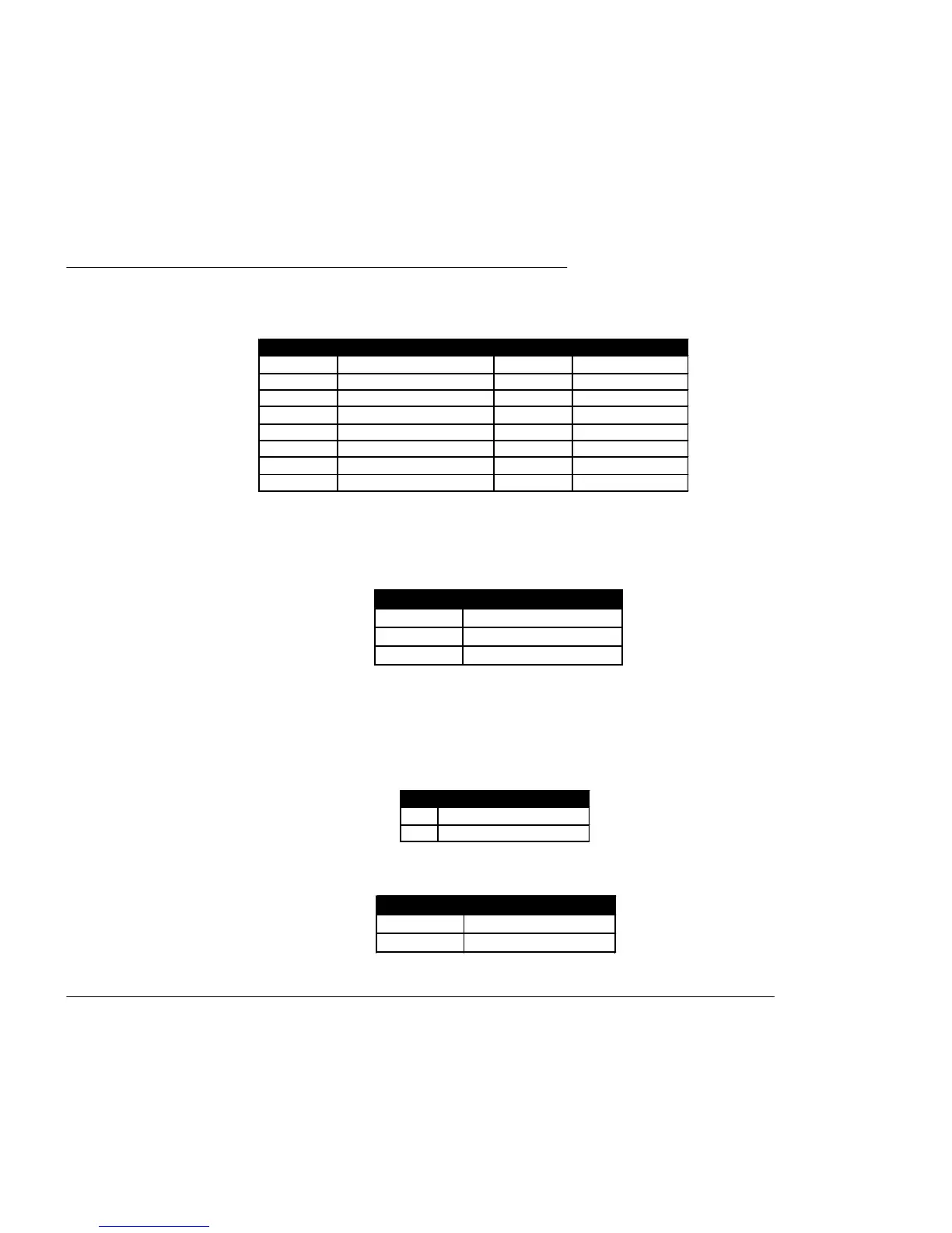
J5 - Interboard sync connector
Cable available from Digigram upon request.
Switches
SW1 - Input impedance (all switches must be set together)
SW2 - Inter board sync switch (all switches must be set together)
Options : Analog and digital break out cables are available on request.
pin # Signal pin # Signal
1 GPI Out 1 A 9 GND
2 AES/EBU IN 2 – 10 LTC IN
3 AES/EBU IN 2 + 11 GPI Out 1 B
4 AES/EBU SYNC/ IN 1 – 12 GPI Out 2 A
5 AES/EBU SYNC/ IN 1 + 13 GPI Out 2 B
6 GPI Input 2 14 AES/EBU OUT+
7 GND/ GPI Input Common 15 AES/EBU OUT –
8
GPI Input 1
Pos. input impedance
OFF > 10 kOhm
ON 600 Ohm
Pos. Description
OFF Slave card
ON Master card
pin # Description
1 Left
2, 3 Ground
4 Right
J3 - Digital connector (Sub-D 15 High density, female)
J4 - CDinput connector

Related product manuals