EasyManua.ls Logo

Digikeijs DIGIBOOST DR5033 - User Manual

Digikeijs DIGIBOOST DR5033
18 pages
Print Icon
To Next Page IconTo Next Page
Loading...
DR5033 DIGIBOOST


  !"#$%&
$'()(*
DR5033
DIGIBOOST
instrucon manual
(2019-10-14)
+,"-'((./'()#0
1#2-"
-""3
"4
Question and Answer IconNeed help?

Do you have a question about the Digikeijs DIGIBOOST DR5033 and is the answer not in the manual?

Summary

Warranty and Warranty Conditions

Legal Information

Product Overview

General Product Information

Details about the DR5033 booster's capabilities and compatibility with DCC and Railcom®.

Technical Specifications

Defines the terminal specifications, cross-section, and electrical characteristics of the DR5033.

Hardware Overview

Adjusting DR5033 Configuration

LocoNet Variables (LNCV) Table

List of LocoNet variables (LNCVs) with their ranges, default values, and descriptions for booster configuration.

LNCV 3 Configuration Description

Details the bit settings within LNCV 3 to customize booster behavior like short-circuit response and startup.

Connection Examples

Important Notes for DR5033 Usage

Key operational considerations, warnings, and requirements for using the DR5033 booster safely.

Tested Central Units and Connection Types

Compatibility and recommended connection methods for various DCC central units like DR5000, Roco z21, and Uhlenbrock Intellibox.

DR5000, DR5033 Boosters and DR4088 Modules

Diagram showing connections between the DR5000 command station, DR5033 boosters, and DR4088 feedback modules.

DR5000, DR5033 Boosters and DR5088 RC Modules

Wiring diagram for connecting the DR5000, DR5033 boosters, and DR5088RC feedback modules.

DR5000, DR5033 Boosters and DR4088 xx Modules

Connection diagram illustrating the setup with DR5000, DR5033 boosters, and DR4088xx feedback modules.

Roco z21;z21 Start DR5033 via B-Bus Connection

Illustrates connecting the DR5033 to Roco z21/z21Start systems using the B-Bus for track power distribution.

Roco Z21 DR5033 via B-Bus Connection

Diagram for connecting the DR5033 to Roco Z21 systems via the B-Bus, showing multiple booster connections.

Lenz Central DR5033 via CDE Connector

Wiring example for connecting Lenz central units (LZ100, LZ200) to the DR5033 using the CDE connector.

Uhlenbrock Intellibox DR5033 via LocoNet B

Shows how to connect the DR5033 to Uhlenbrock Intellibox systems via LocoNet B, with critical safety warnings.

H-bridge Control Panel DR5033 via Track Sniffer

Demonstrates connecting the DR5033 to any H-bridge control panel using the Track Sniffer input for signal detection.

Overview

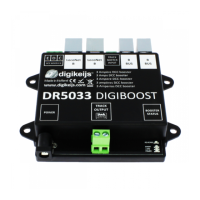
The DR5033 DIGIBOOST is a pure DCC booster designed for model railway systems, capable of handling Railcom®. It is an H-bridge booster offering various connection options to integrate with an existing central unit, including CDE booster connection, LocoNet® B, Roco® booster bus, and track sniffer. The device's configuration is highly customizable through LNCV programming, allowing users to adapt its behavior, such as short-circuit response, start-up behavior, and automatic polarity reversal.

Function Description:

The DR5033 DIGIBOOST acts as a power amplifier for DCC signals, extending the reach and current capacity of a central unit. It supports Railcom® functionality, enabling feedback from locomotives on the track. The booster can be configured to automatically switch the polarity of the track output or respond to magnetic commands for polarity changes. Additionally, it can be switched on and off separately via a magnetic command, and its current status can be queried by the control panel.

Important Technical Specifications:

  • Outputs: Track Out, with a loading capacity of 3A.
  • Inputs: LocoNet® B, Track Sniffer, Roco® Booster Bus.
  • Power Supply: 15-19V DC, 3A.
  • Terminals: Designed for a cross-section of 0.75mm².
  • Warranty: 24-month manufacturer's warranty. Opening the housing voids the warranty.
  • Unsupported Protocols: Märklin® Mfx® and other non-DCC protocols are not supported.
  • Compatibility Warning: The DR5033 must not be used in systems that operate according to the common ground principle, as this can lead to the destruction of the booster and/or the central unit. This is particularly important when connecting to control panels like Uhlenbrock® Intellibox® or Piko® Smart ControllerLight®. Track separation on both sides is not sufficient in such cases.
  • Transition Voltage: The transition voltage between booster ranges must always be less than 0.8 Volt, verifiable with a multimeter. If exceeded, the input voltage of the booster or the central unit's voltage setting must be adjusted.
  • Roco® B-Bus® Limitation: The maximum number of boosters on the Roco® B-Bus® is limited to four.

Usage Features:

  • Configuration: All settings, including LocoNet® module address and magnetic article address, are adjusted via LNCV programming through the DR5000's "LNCV Programming" menu under LocoNet B.
  • LNCV 3 Configuration: This LNCV allows adaptation of the booster's behavior, including short-circuit behavior, start behavior, and automatic reverse polarity.
  • Module Address: The default LocoNet module address is 1 (range 1-9999). If multiple DR5033s are used or the address is unknown, only one DR5033 should be connected at a time for programming.
  • Booster Status LED: Provides visual feedback on the booster's operational status:
    • Green: Track signal present (normal operation).
    • No LED: No track signal present (check LocoNet® B, B-Bus, CDE, Track Sniffer Input).
    • Yellow (dim): Booster load under 90% (LED brightens with load).
    • Yellow (bright): Booster load greater than 90%.
    • Red: Short circuit detected.
    • Red/Green flashing: Stop command detected (e.g., by the control unit).
    • Blue: Track Out reversed polarity. This indicates reversed polarity if the blue LED lights up when driving over booster separation points.
  • Connection Examples: The manual provides detailed diagrams for connecting the DR5033 with various central units and feedback modules, including:
    • DR5000, DR5033 Boosters and Feedback Modules (DR4088, DR5088RC, DR4088xx).
    • Roco® z21®, z21Start® via R-Bus®.
    • Lenz Central® via CDE connection.
    • Uhlenbrock Intellibox® via LocoNet® B.
    • Any H-bridge control panel via Track Sniffer.
  • Railcom® Integration: When connected to a DR5000 via LocoNet® B, Railcom® is generated by the DR5000 and passed to the booster. The DR5033's status can be queried via LocoNet®, and it can be individually switched off/on via a magnetic article address.
  • CDE Booster Connection: Ensure the CDE connection of the control panel complies with Lenz® specifications.

Maintenance Features:

  • Firmware Version: The firmware version (LNCV 1) can be read from the device.
  • Temperature and Load Monitoring: The temperature of the H-bridge in degrees °C (LNCV 6) and current load in % (LNCV 7) can be read, providing insights into the booster's operational health.
  • Short-Circuit Restart Time: The waiting time until restart after a short circuit (LNCV 11) is configurable, with a default of approximately 750 ms (244 in 3-millisecond steps).
  • Polarity Reversal Timing: Configurable waiting times for automatic polarity reversal (LNCV 12) and before polarity reversal or short-circuit signal (LNCV 13).

Digikeijs DIGIBOOST DR5033 Specifications

General IconGeneral
BrandDigikeijs
ModelDIGIBOOST DR5033
CategoryExtender
LanguageEnglish

Related product manuals