Basys2™ FPGA Board Reference Manual
Copyright Digilent, Inc. All rights reserved.
Other product and company names mentioned may be trademarks of their respective owners.
5.1 Keyboard
The keyboard uses open-collector drivers so the keyboard or an
attached host device can drive the two-wire bus (if the host
device will not send data to the keyboard, then the host can use
input-only ports).
PS2-style keyboards use scan codes to communicate key press
data. Each key is assigned a code that is sent whenever the key
is pressed; if the key is held down, the scan code will be sent
repeatedly about once every 100ms. When a key is released, a
“F0” key-up code is sent, followed by the scan code of the
released key. If a key can be “shifted” to produce a new character (like a capital letter), then a shift character is
sent in addition to the scan code, and the host must determine which ASCII character to use. Some keys, called
extended keys, send an “E0” ahead of the scan code (and they may send more than one scan code). When an
extended key is released, an “E0 F0” key-up code is sent, followed by the scan code. Scan codes for most keys are
shown in the figure. A host device can also send data to the keyboard. Below is a short list of some common
commands a host might send.
ED Set Num Lock, Caps Lock, and Scroll Lock LEDs. Keyboard returns “FA” after receiving “ED”, then host
sends a byte to set LED status: Bit 0 sets Scroll Lock; bit 1 sets Num Lock; and Bit 2 sets Caps lock. Bits 3 to
7 are ignored.
EE Echo (test). Keyboard returns “EE” after receiving “EE”.
F3 Set scan code repeat rate. Keyboard returns “F3” on receiving “FA”, then host sends second byte to set
the repeat rate.
FE Resend. “FE” directs keyboard to re-send most recent scan code.
FF Reset. Resets the keyboard.
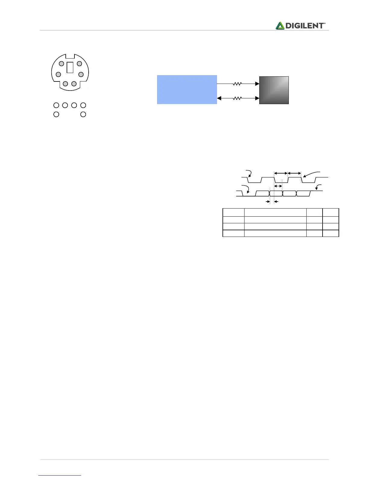
The keyboard can send data to the host only when both the data and clock lines are high (or idle). Since the host is
the “bus master”, the keyboard must check to see whether the host is sending data before driving the bus. To
facilitate this, the clock line is used as a “clear to send” signal. If the host pulls the clock line low, the keyboard
must not send any data until the clock is released.
T
CK
T
SU
Clock time
Data-to-clock setup time
30us
5us
50us
25us
Symbol Parameter Min Max
T
HLD
Clock-to-data hold time 5us 25us
Edge 0
‘0’ start bit ‘1’ stop bit
Edge 10
Tsu
Thld
Tck Tck
Figure 10. PS/2 signal timing
Pin1: Data
Pin2: Data
Pin3: GND
Pin5: Vdd
Pin6: Clock
Pin8: Clock
2 1 35
8 6
1
3
6
2
5
8
(bottom up)
B1
Spartan 3E
FPGA
CLK
DATA
6-pin
mini-DIN
C3
200 W
200 W
Figure 9. PS/2 connector and Basys 2 PS/2 circuit.
 Loading...