JTAG-HS2 Reference Manual
Doc: 502-249 page 3 of 5
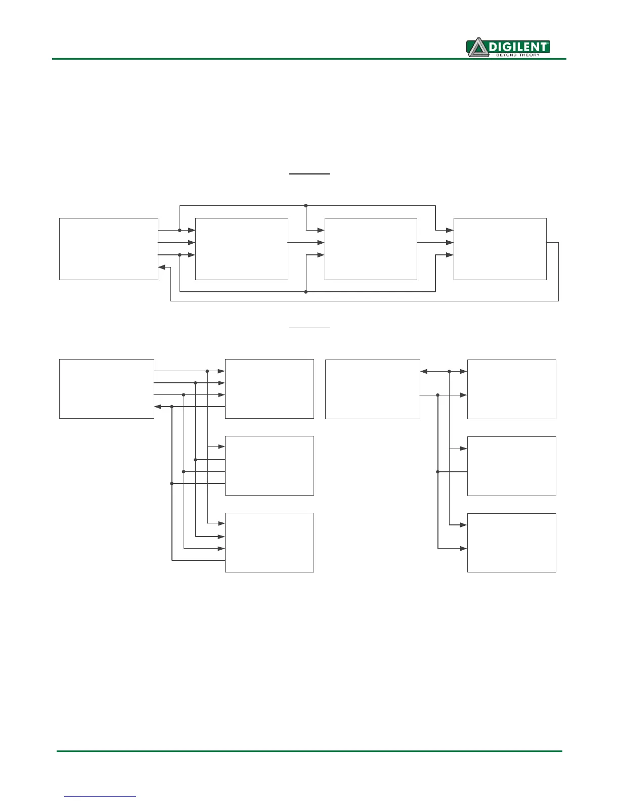
IEEE 1149.7-2009 Compatibility
The JTAG-HS2 supports several scan formats including; the JScan0-JScan3, MScan, and OScan0 -
OScan7. It is capable of communicating in 4-wire and 2-wire scan chains that consist of Class T0 –
T4 JTAG Target Systems (TS). (See Figure 5 & 6)
Figure 5
TMS
TDI
TCK
TDO
Host
+
JTAG-HS2
(DTS)
TMS
TDI
TCK
TDO
Target
System 0
TMS
TDI
TCK
TDO
Target
System 1
TMS
TDI
TCK
TDO
Target
System N
4-Wire Series Topology
Figure 6
TMSC
TDIC
TCKC
TDOC
Target
System 0
Target
System 1
Target
System N
4-Wire Star Topology
TMSC
TDIC
TCKC
TDOC
TMSC
TDIC
TCKC
TDOC
TMS
TDI
TCK
TDO
Host
+
JTAG-HS2
(DTS)
2 - W i r e S t a r T o p o l o g y
T M S C
T D I C
T C K C
T D O C
T a r g e t
S y s t e m 0
T a r g e t
S y s t e m 1
T a r g e t
S y s t e m N
T M S C
T D I C
T C K C
T D O C
T M S C
T D I C
T C K C
T D O C
T M S
T D I
T C K
T D O
H o s t
+
J T A G - H S 2
( D T S )
The Adept SDK provides an example application that demonstrates how to communicate with a
Class T4 TAP controller using the MScan, OScan0, and OScan1 scan formats.
Design Notes
The JTAG-HS2 uses high speed three-state buffers to drive the TMS, TDI, and TCK signals. These
buffers are capable of sourcing or sinking a maximum of 50 mA of current. The HS2 has 100 ohm
resistors between the output of the buffers and the I/O pins to ensure the cable does not exceed the
maximum limit. To further limit short circuit current additional resistance may be placed in series with
the I/O pins of the HS2 and the target board. However, Digilent recommends limiting the amount of
additional resistance to 100 ohms or less as higher resistance may result in degraded operation.
 Loading...