EasyManua.ls Logo

DIGISYNTHETIC DP1400 User Manual

Default Icon
10 pages
To Next Page IconTo Next Page
Page #1 background imageLoading...
Page #1 background image
USER MANUAL
POWER
EXCELLENT POWER AMPLIFIER
DIGISYNTHETIC
R
DP4800
DP3200
DP2240
DP1800
DP1400
CLIP
SIGNAL
PROTECT
Channel A Channel B
DP Series
Power Amplifier
PROPRO
CLIPCLIP
BRIDGEBRIDGE
ONON
CH CCH C
CH DCH DCH ACH A
CH BCH B
DP 4800
-4
-18
-21
-14
-24
-8
-28
-36
-2
0
-¡Þ
-18
-21
-14
-24
-8
-28
-36
-2
0
-¡Þ
-18
-21
-14
-24
-8
-28
-36
-2
0
-¡Þ
-18
-21
-14
-24
-8
-28
-36
-2
0
-¡Þ
PROTECT
SIG/CLIP
BRIDGE
PROTECT
SIG/CLIP
BRIDGE
DP 3200
Question and Answer IconNeed help?

Do you have a question about the DIGISYNTHETIC DP1400 and is the answer not in the manual?

DIGISYNTHETIC DP1400 Specifications

General IconGeneral
BrandDIGISYNTHETIC
ModelDP1400
CategoryAmplifier
LanguageEnglish

Summary

DP Series Power Amplifier Introduction

Important Safety Instructions

General Safety Precautions

Basic precautions for using electric products, including supervision and location.

Electrical Safety and Grounding

Dangers of improper grounding and importance of proper outlets and plugs.

Operational Hazards and Precautions

Risks related to water, sound levels, heat sources, cord handling, and tripping.

Installation and Operating Instructions

Mains Power Connection

Connecting the amplifier to the mains power socket, checking voltage.

Switching On and Off Procedure

Recommended sequence for switching power amplifiers on and off in an audio system.

Handling and Cable Management

Advice on handling components and caring for connector cables.

Interference Prevention and Air Circulation

Avoiding interference, managing earth loops, and ensuring proper ventilation.

Product Features Overview

Control Panel - Front and Protection

Front Panel Controls and Indicators

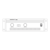
Explains power switch, level controls, and front panel indicator LEDs.

Protection Circuitry Details

Details on Thermal, Voltage, and Circuit Damage protections.

Control Panel - Rear and Operation Details

Limit, Signal, and Bridge LEDs

Explains Limit, Signal, and Bridge status LEDs and switch functionality.

Rear Panel Connectors Overview

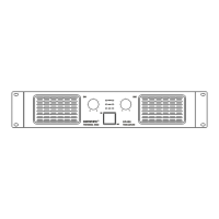
Illustration and labeling of rear panel input/output connectors and power input.

Rear Panel Functions Explained

Rear Panel Layout Diagram

Detailed illustration of the rear panel with numbered connection points.

Operational Modes and Connections

Outputs and Grounding Selector

Details speaker outputs and the grounding selector function.

Stereo/Bridge Selector and Inputs

Explains stereo/bridge mode and balanced signal inputs.

Connector Cable Guide

Specifications