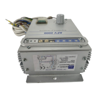
The Digisystem srl AFV2000 is a variable frequency vibrator power supply designed to maintain vibration in a fed system by providing the necessary energy precisely when needed. Its primary application is to power the excitation coils of electromagnets used in vibrating systems, such as linear and circular feeders, commonly found in automation systems. Unlike traditional feeders that supply a fixed frequency based on power mains, the AFV2000 allows for adjustable feeding frequency, which is crucial for achieving resonance conditions.
Function Description
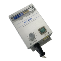
The AFV2000's core function is to adjust the feeding frequency to match the springset's resonance condition. This eliminates the need for extensive mechanical adjustments to the springset, which is often a complicated and imprecise process. By regulating four rotating switches on the front panel, users can easily change the feeding frequency. This adjustment can be made while the system is in motion, allowing for quick optimization of feeding performance. The device also helps maintain consistent system performance over time, as springsets can change their elasticity due to material enervation.
The vibration intensity can be regulated either with a potentiometer or through a 0-5V voltage reference. Minimum and maximum intensity limits can be set using trimmers (MIN and MAX) accessible on the front panel. The device includes electronic overload protection with an auto-reset feature, signaled by a red LED. It is shipped with an autostart function enabled by default (SW2 switch on the front panel in the "up" position).
Important Technical Specifications
- Power Supply: 230Vac ± 15%, 50 or 60 Hz frequency.
- Output Voltage: Adjustable from 50 to 220Vca (with a 230Vca power supply).
- Output Compensation: Features compensation for power supply variations.
- Output Frequency: Adjustable from 3.0 to 199.9 Hz in 0.1 Hz steps.
- Current: Maximum current of 12 Amperes peak (approximately 5 Arms), limited by an auto-reset circuit.
- Fuses: 6.3 A fast-action 250Vac, dimensions 5x20.
- Voltage Output: Soft-start with a ramp.
- Remote Commands:
- Start/stop with external PNP voltage (15 ÷ 30 Vdc, 10 mA current) via optocoupler.
- External potentiometer (see page 9 for wiring).
- Voltage reference 0 ÷ 5 Vdc (see page 9 for wiring).
- Current reference 0 ÷ 20 mA (see page 9 for wiring).
- Start/stop NPN (see page 9 for wiring).
- Mechanical Protection: IP 20.
- EMI Protection: Meets LVD CEI EN60439-1, EMC CEI EN50082-2, and EMC CEI EN50081-2 standards, provided wiring instructions are followed.
- Dimensions: 255 x 120 x 76 mm (height, breadth, depth). An additional 20-30mm clearance is required on the lower side for connector insertion.
- Weight: 1.4 Kg.
Usage Features
The AFV2000 is designed for ease of installation and use. It is compact and can be fixed to a supporting structure using two 6mm diameter holes. Electrical connections are made via 6-pole and 9-pole terminal boxes.
Startup Procedure:
- Ensure the mains breaker is in the OFF position.
- Set the voltage reference to approximately 20%.
- Verify the status of switch SW2 (red lever): "up" enables autostart on power-on; "down" requires an external start command.
- Confirm that trimmer P1 (min) is fully counterclockwise and P2 (max) is fully clockwise.
- Ensure all connections are secure.
- Set the rotating switches SW1 to 050.0 for a 50.0 Hz output frequency.
- Connect the mains breaker (230 Vac).
- If the start command is active, the vibrator will be supplied at the selected frequency (e.g., 50 Hz) and voltage defined by the voltage reference.
Finding Resonance:
The resonance frequency is typically found by observing the effects on product feeding while adjusting the SW1 values. For a 50 Hz vibrator, resonance usually falls between 45 and 55 Hz. Even small frequency changes can significantly alter speed. Users should proceed with iterative adjustments until the SW1 position that achieves resonance is found. Once resonance is reached, the reference value can be increased or decreased to obtain the desired vibration level. During the search phase, it is recommended to keep the reference voltage at 20% of the end of scale (about 1 volt).
Overload Indication:
If, while increasing the reference value, the green LED DL1 switches off and the red LED DL2 switches on, and the vibrator stops, it indicates an overload. In this case, the reference value should be decreased, and the power supply will automatically reset the overload condition.
Remote Control Options:
The device supports various remote control methods:
- External Voltage Generator: Connect 0V to pin 6 and the reference to pin 8.
- External Potentiometer (10K): Connect the sliding contact to pin 7, CW to pin 5, and CCW to pin 6.
- Current Reference (0-20 mA): Connect 0V to pin 4 and the reference to pin 9. Pins 8 and 9 must be shorted.
- Start/Stop Control: SW2 on the front panel selects between automatic start (power-on) and remote start/stop via an external command. The device ships with autostart ON.
- External Sensor (PNP/NPN): A supply of 18V 50mA (unstabilized) is available for sensors.
- PNP Sensor: Connect sensor supply between pins 1 (+18V) and 4 (0V), and the sensor signal to pin 3.
- NPN Sensor: Connect sensor supply between pins 1 (+18V) and 4 (0V), and the sensor signal to pin 3. Change jumper H4 from P to N (located inside the box).
- Inverter OK Signal: A PNP (18V 20mA) signal is available at pin 2 for remote checking of the power supply status (pin 4 is 0V).
Maintenance Features
Troubleshooting:
The manual provides a table for common problems and their solutions:
- Led DL2 switches regularly on and off (Overload condition): Decrease reference voltage to reduce output power.
- At power on, Led DL2 doesn't switch momentarily on, and DL1 doesn't switch at all (Device not supplied): Verify mains supply and input fuses.
- At power on, Led DL1 is off, Led DL2 switches momentarily on, but vibration doesn't start (No start command): Place switch SW2 to ON or send a start command from the input cable.
- At power on, Led DL1 switches on, Led DL2 switches momentarily on, but vibration doesn't start (Vibrator not supplied): Check wiring from the power supply to the vibrator. If wiring is correct, there might be a failure in the power supply drivers.
For issues not resolved by the troubleshooting table, users are advised to contact Digisystem srl via email.
Opening Instructions (for maintenance/fuse replacement):
- Safety Warning: Due to high voltage capacitors on the electronic card, there is a risk of electrical shock from residual energy. Wait at least 4-5 minutes after disconnecting the device from the power supply before opening the box.
- Procedure: Remove the four screws on the panel.
Wiring Precautions:
- The vibrator's ground must be connected with an appropriate wire.
- Before supplying power, verify that there are no ground dispersions on the wires connecting the power supply to the vibrator. Grounding one of the two output wires will damage the power supply.