Page 1 of 4
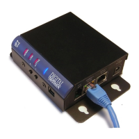
IP7-FX
SIP Getting Started Guide
Introduction
The IP7-FX is a PoE powered (802.3af) IP Audio Module that can be configured as a SIP extension for use with a
SIP based phone system. The module can connect to an analog audio device such as a call station or speaker and
provides the following features
• Ethernet 10/100 Network Connector
• Port 2 10/100 available to connect another device to the network
• Eight-watt amplifier
• Microphone or Line In
• Speaker or Line Out
• Two input signals (Call and Sensor)
• Normally Open or Normally Closed Dry Contact Relay (250 VAC /
30VDC @ 60W / 1500 VAC Isolation)
• PoE (802.3af), 12VDC or 24VDC
• User configurable Full or Half duplex operation
• Standard 35MM DIN Rail Mount or optional Surface Mount Plate (included)
The IP7-FX can be configured using the eSIP Configuration utility or the TalkMaster Administrator console. This
Getting Started Guide covers basic hardware installation and software configuration of the IP7-FX.
Replacing an IP7-ST/STx, SS8/SE8, FD or SS20
If the IP7-FX is being used to replace an existing IP7-ST/STX, IP7-SS8/SE8, IP7-FD or an IP7-SS20, please note the
following:
• The J3-7 (Case) connector on older models was an extra ground. If replacing an older model with an IP7-
FX, any wire connected to J3-7 should be moved to J3-6.
• If replacing an IP7-ST/STx, make sure the internal ST-MIC switch (located on the DIN clip side) is set in
the same position. The IP7-FX does not support the Aiphone IE/ IF series call station. An IP7-ST/STx
must be used
• If the older IP7’s J2-6 (SPKR 8Ω+) and J2-7 (SPKR 8Ω-) is connected to an amplifier or amplified
speaker, use the IP7-FX’s J2-3 (Line Out) and J2-4 (GND) instead
• If replacing an IP7-SE8 / IP7-MSR-BRD with an IP7-FX, the IP7-MSR-BRD can be eliminated by changing
the IP7-FX’s ST-MIC internal switch to the ST position
• Other than the exceptions noted above, the J1, J2, J3, and network can be moved over to the IP7-FX