Do you have a question about the Digital Equipment 5220 Series and is the answer not in the manual?
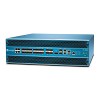
Describes the DIGITAL Server 5220 as a high-performance, scalable network and application server.
Details features supporting server uptime and data integrity.
Lists expansion capabilities like PCI slots and storage options.
Covers server diagnostics, configuration, and security features.
Explains naming conventions for DIGITAL Server products.
Details the system for assigning product model numbers.
Lists available documentation and their order numbers.
Provides web addresses for product info and updates.
Overviews the utilities supplied with the server.
Describes software for NOS installation and utilities.
Utility for configuring server hardware and BIOS settings.
Step-by-step guide to enter and use the BIOS Setup utility.
Provides tips and keyboard shortcuts for using BIOS Setup.
General section for configuration changes.
Procedure to set the system's time and date.
How to modify I/O port configurations via BIOS.
Information on managing IRQ assignments for expansion boards.
Details interrupt assignments for PCI slots.
Table showing PCI interrupt routing.
Overview of server security features.
How to set passwords for BIOS access.
Steps to enable password prompt during server boot.
Procedure to remove set passwords.
Discusses additional security settings like Sign On Banner.
How to modify the server's boot order.
Options to accelerate server startup time.
Accessing system and environment parameters.
Procedure for updating the server's BIOS.
Utility to configure onboard SCSI controller settings.
How to check connected SCSI devices.
Utility for configuring RAID arrays.
Overview of diagnostic software for verifying server operation.
Introduces BIOS utility for editing resources and configuring the server.
Explains the BIOS Setup utility and its main screen.
Details the 'Main' menu options in BIOS Setup.
Covers cache and shadow RAM settings for performance.
BIOS settings related to keyboard behavior.
Overview of advanced configuration options in BIOS Setup.
Settings for integrated peripherals like IDE, serial, parallel.
Configuration for chipset features like ACPI and ECC.
Settings for PCI device IRQ assignments.
Settings for system security like passwords.
BIOS settings related to the boot process.
Section for system management utilities.
Displays a summary of system information.
Monitors server environment like temperature and voltage.
Details memory slot configuration and status.
Displays POST error summaries.
Manages system asset numbers and I/O.
Manages asset numbers for the processor module.
Shows the status of PCI IRQ assignments.
Introduces troubleshooting procedures for the server.
General procedures for initial troubleshooting steps.
Guidelines on when to run diagnostic software.
Steps to run the AMIDiag base package.
How to run specific diagnostic tests or groups.
How to run extended diagnostic tests from diskette.
Steps to run diagnostics from the server's HDD.
How to get system information from the server.
How to get server info via BIOS Setup.
Overview of the ServerWORKS Manager software.
How to view server status indicators.
Lists status messages and possible failures.
Lists POST and OCP panel messages.
Tables of POST/Boot codes for the processor.
Displays POST messages related to the processor module.
Discusses OCP panel messages and hot keys.
Lists OCP status and error messages.
Lists voltage and temperature ranges for the processor.
Details normal, error, and shutdown voltage values.
Specifies Vccp voltage ranges for different modes.
Describes temperature monitoring and failure results.
Introduces CRU process and general troubleshooting tips.
Tables listing server problems, causes, and actions.
Troubleshooting for internal SCSI devices.
Troubleshooting for hot swap drive LEDs.
Troubleshooting steps for tape drive issues.
Troubleshooting for monitor display issues.
Troubleshooting steps for CD-ROM drive problems.
Troubleshooting for diskette drive read/write issues.
Troubleshooting for RAID adapter and drive issues.
Troubleshooting for BIOS flashing issues.
Lists FRU part numbers and replacement procedures.
Identifies components visible from the server's front.
Identifies components visible from the server's left side.
Identifies components visible from the right/rear.
Lists various optional parts and adapters.
Details server labels and nameplates.
General service instructions and safety precautions.
Lists essential tools for service procedures.
Provides URL for BIOS upgrade information.
Steps to safely disconnect power and peripherals.
Procedure for removing and installing server side panels.
Components of the server's front view.
Components of the server's left side view.
Components of the server's right side view.
Components of the server's rear view.
Identifies connectors on the main logic board.
Identifies main logic board components.
Identifies processor module components.
Details connectors on the video/Ethernet daughter card.
Lists main logic board jumper and switch settings.
Lists switch settings for processor speed.
Steps for installing more memory modules.
Specifies requirements for server memory modules.
Guidelines for installing memory modules.
Examples of memory configurations and mixing sizes.
How to troubleshoot memory errors detected by POST.
Procedure for replacing the server's power supply.
Steps to remove and replace the diskette drive.
Procedure for replacing the CD-ROM drive.
Steps to remove and replace cooling fans.
Steps to replace secondary cooling fan 2.
Steps to remove and replace cooling fan 5.
Procedure for removing and replacing the speaker.
Detailed steps to replace the main logic board.
Procedure to replace the RTC battery.
Steps to remove and replace the storage backplane.
Procedure to remove and replace server casters.
Introduces tables for memory and address information.
Table showing memory address ranges and their functions.
Table detailing I/O address map for various devices.
Lists interrupt numbers and their sources.
Map of PCI configuration space addresses.
Compares features of Server 5200 and 5220 models.
Steps to perform a server upgrade.
Guidelines for troubleshooting after an upgrade.
Describes the main logic board block diagram.
Details the CPU/Memory connector pinout.
Describes the PIIX4 chip functionality.
Information about the BIOS ROM.
Describes the system input/output controller.
Details the Ultra I/O controller's functions.
Information on serial interface ports and pin assignments.
Pin assignments for serial interface ports.
Describes the parallel interface and its modes.
Pin assignments for the parallel interface.
Details the integrated diskette controller.
Describes the keyboard/mouse controller.
Pin assignments for keyboard/mouse connectors.
Details the PCI SCSI interface.
Describes the PCI SCSI controller.
Details SCSI connectors on the main logic board.
Describes the standard and PCI IDE interfaces.
Overview of the video display interface.
Details the SVGA video controller.
Pin assignments for the SVGA connector.
Details the Ethernet interface controller.
Pin assignments for the network interface.
Overview of the PCI bus architecture.
Details PCI bus expansion slots.
Describes the PCI-to-PCI bridge chip.
Details the ISA bus specifications.
Describes the system management subsystem.
Lists tested and certified options for the server.
| Brand | Digital Equipment |
|---|---|
| Model | 5220 Series |
| Category | Server |
| Language | English |