UltraBlock™ USB User Manual 2
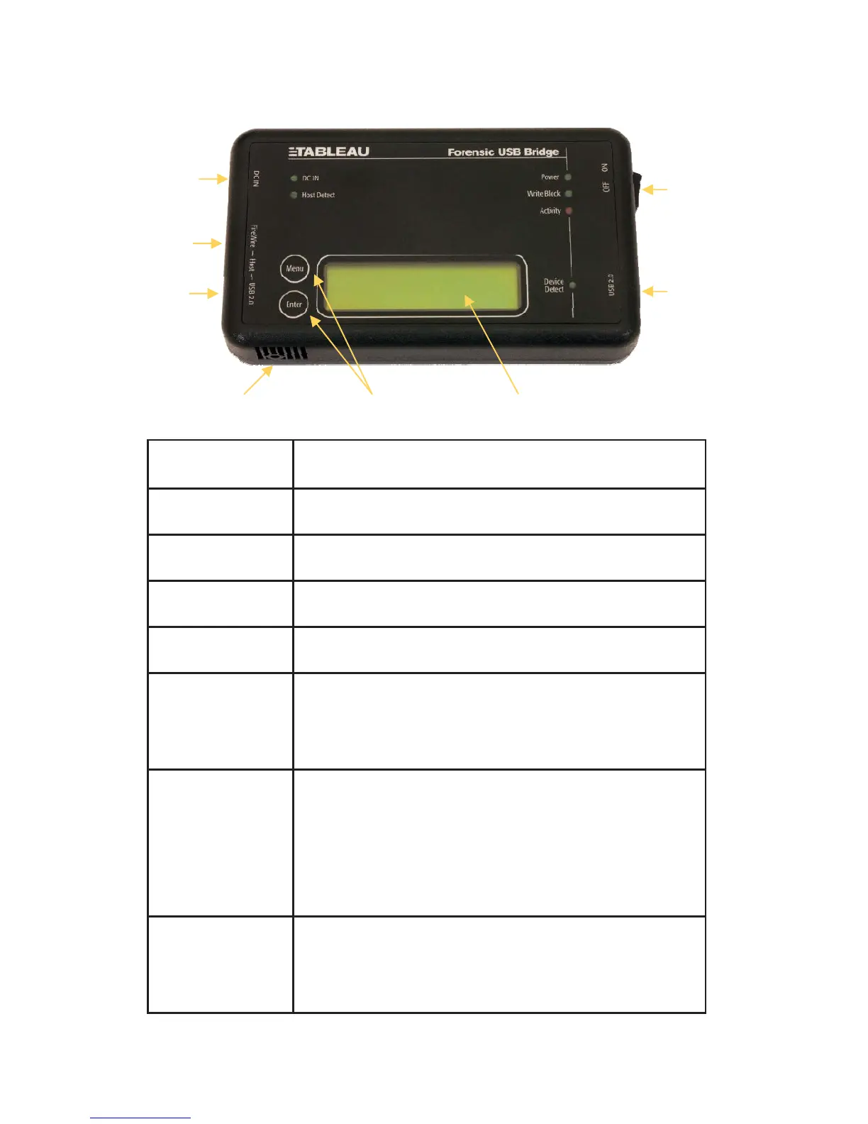
DC IN The DC IN connector on the UltraBlock USB is compatible
with the output of the UltraBlock power supply.
ON/OFF Switch The ON/OFF switch controls power to the UltraBlock USB
and USB device attached to the USB 2.0 (device) connector.
USB 2.0 (device) Plug the device to be write-blocked into the USB 2.0
(device) connector.
LCD Display The LCD display shows the current status of the UltraBlock
USB, including whether or not a USB device has been suc-
cessfully recognized by the UltraBlock USB. Using the Ul-
traBlock USB buttons (see below), the user may also navi-
gate additional information screens shown on the display.
LCD
Contrast Adjustment
The LCD contrast is already set for normal viewing when the
UltraBlock USB is shipped from the factory. However, you
may need or want to adjust the LCD contrast to suit your
preferences or work environment. To adjust the
LCD contrast, carefully insert a #0 phillips head screwdriver
in the hole as shown in the above image. To make the dis-
play darker, rotate the screwdriver counter-clockwise. To
make the display lighter, rotate the screwdriver clockwise.
Buttons The UltraBlock USB has two buttons, "Menu" and "Enter."
These two buttons may be used to navigate additional infor-
mation screens on the LCD display. The arrangement of
information viewable on the LCD display is described later in
this document.
USB 2.0 (host) USB 2.0 connector. Used when connecting the UltraBlock
USB to a host computer via USB 2.0.
FireWire (host) FireWire400/1394A connector. Used when connecting
the UltraBlock USB to a host computer via FireWire/1394.
DC IN
FireWire
(host)
USB 2.0
(host)
LCD Contrast
Adjustment
Buttons LCD Display
USB 2.0
(device)
ON/OFF
Switch