DigitAx User Guide
Issue code: dgxu4
4-3
≥3mm
( in)
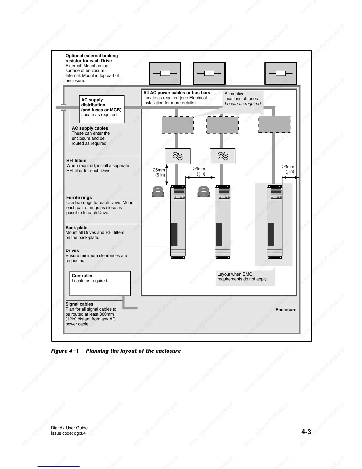
Optional external braking
resistor for each Drive
External: Mount on top
surface of enclosure.
Internal: Mount in top part of
enclosure.
Controller
Locate as required.
Signal cables
Plan for all signal cables to
be routed at least 300mm
(12in) distant from any AC
power cable.
Drives
Ensure minimum clearances are
respected.
RFI filters
When required, install a separate
RFI filter for each Drive.
AC supply cables
These can enter the
enclosure and be
routed as required.
AC supply
distribution
(and fuses or MCB)
Locate as required.
All AC power cables or bus-bars
Locate as required (see Electrical
Installation for more details)
Enclosure
Layout when EMC
requirements do not apply
Alternative
locations of fuses
Locate as required
125mm
(5 in)
Back-plate
Mount all Drives and RFI filters
on the back-plate.
≥3mm
( in)
Ferrite rings
Use two rings for each Drive. Mount
each pair of rings as close as
possible to each Drive.
Figure 4–1 Planning the layout of the enclosure
 Loading...