DigitAx User Guide
Issue code: dgxu4
11-8
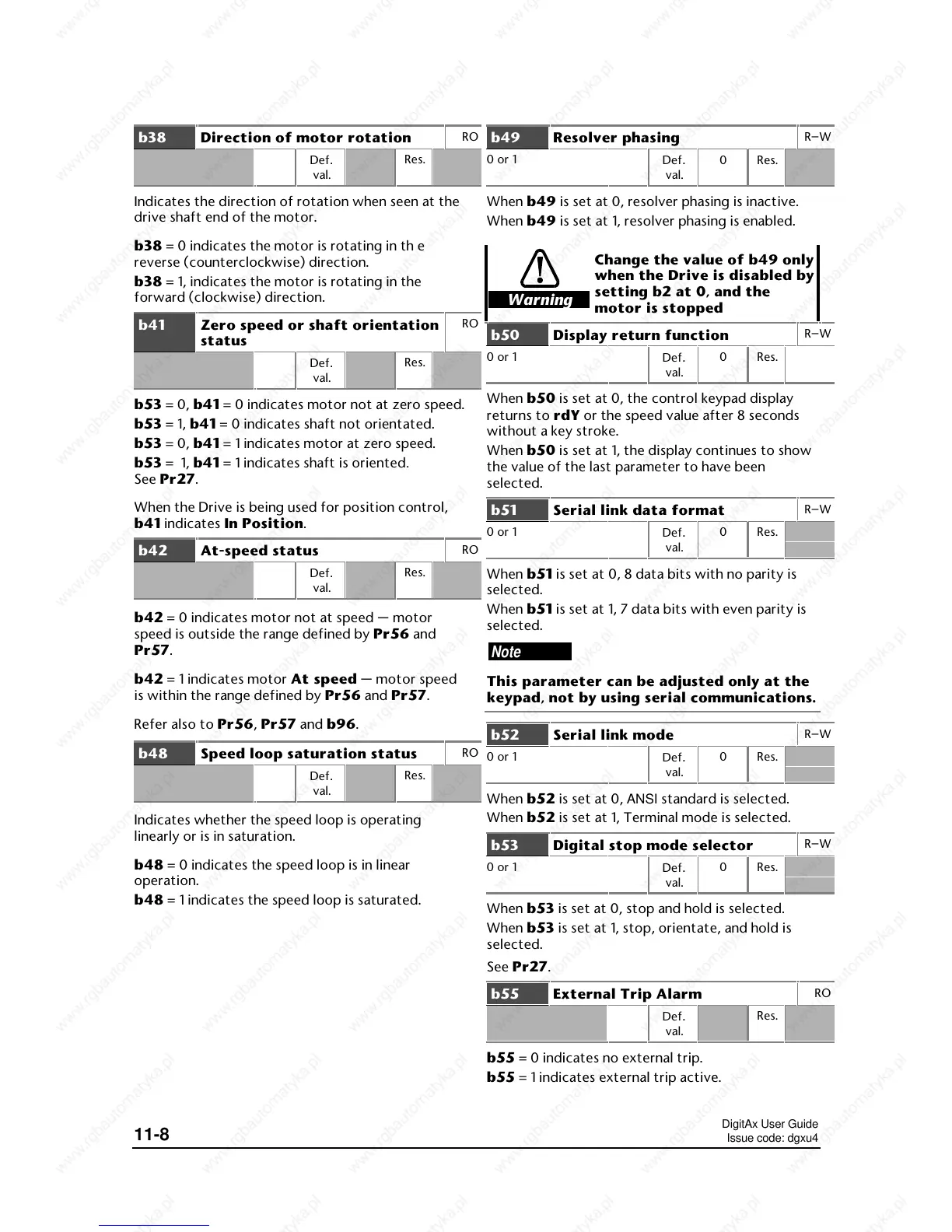
b38 Direction of motor rotation
RO
Def.
val.
Res.
Indicates the direction of rotation when seen at the
drive shaft end of the motor.
b38 = 0 indicates the motor is rotating in th e
reverse (counterclockwise) direction.
b38 = 1, indicates the motor is rotating in the
forward (clockwise) direction.
b41 Zero speed or shaft orientation
status
RO
Def.
val.
Res.
b53 = 0, b41 = 0 indicates motor not at zero speed.
b53 = 1, b41 = 0 indicates shaft not orientated.
b53 = 0, b41 = 1 indicates motor at zero speed.
b53 = 1, b41 = 1 indicates shaft is oriented.
See Pr27.
When the Drive is being used for position control,
b41 indicates In Position.
b42 At-speed status
RO
Def.
val.
Res.
b42 = 0 indicates motor not at speed — motor
speed is outside the range defined by Pr56 and
Pr57.
b42 = 1 indicates motor At speed — motor speed
is within the range defined by Pr56 and Pr57.
Refer also to Pr56, Pr57 and b96.
b48 Speed loop saturation status
RO
Def.
val.
Res.
Indicates whether the speed loop is operating
linearly or is in saturation.
b48 = 0 indicates the speed loop is in linear
operation.
b48 = 1 indicates the speed loop is saturated.
b49 Resolver phasing
R–W
0 or 1
Def
.
val.
0 Res.
When b49 is set at 0, resolver phasing is inactive.
When b49 is set at 1, resolver phasing is enabled.
Warning
Change the value of b49 only
when the Drive is disabled by
setting b2 at 0, and the
motor is stopped
b50 Display return function
R–W
0 or 1
Def
.
val.
0 Res.
When b50 is set at 0, the control keypad display
returns to rdY or the speed value after 8 seconds
without a key stroke.
When b50 is set at 1, the display continues to show
the value of the last parameter to have been
selected.
b51 Serial link data format
R–W
0 or 1
Def
.
val.
0 Res.
When b51 is set at 0, 8 data bits with no parity is
selected.
When b51 is set at 1, 7 data bits with even parity is
selected.
Note
This parameter can be adjusted only at the
keypad, not by using serial communications.
b52 Serial link mode
R–W
0 or 1
Def
.
val.
0 Res.
When b52 is set at 0, ANSI standard is selected.
When b52 is set at 1, Terminal mode is selected.
b53 Digital stop mode selector
R–W
0 or 1
Def
.
val.
0 Res.
When b53 is set at 0, stop and hold is selected.
When b53 is set at 1, stop, orientate, and hold is
selected.
See Pr27.
b55 External Trip Alarm
RO
Def.
val.
Res.
b55 = 0 indicates no external trip.
b55 = 1 indicates external trip active.
 Loading...