DigitAx User Guide
Issue code: dgxu4
5-2
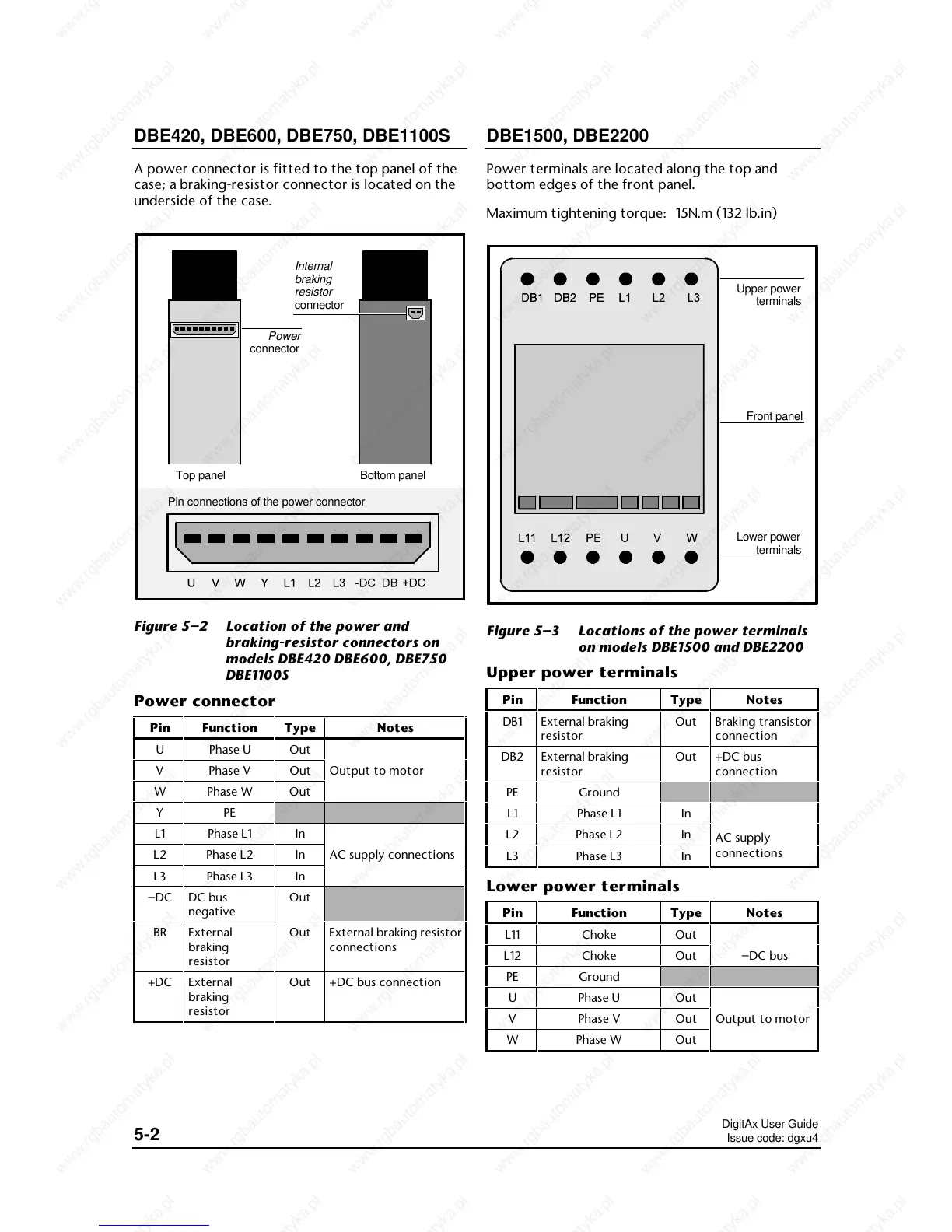
DBE420, DBE600, DBE750, DBE1100S
A power connector is fitted to the top panel of the
case; a braking-resistor connector is located on the
underside of the case.
Power
connector
Top panel
Pin connections of the power connector
Internal
braking
resistor
connector
Bottom panel
Figure 5–2 Location of the power and
braking-resistor connectors on
models DBE420 DBE600, DBE750
DBE1100S
Power connector
Pin Function Type Notes
U Phase U Out
V Phase V Out Output to motor
W Phase W Out
YPE
L1 Phase L1 In
L2 Phase L2 In AC supply connections
L3 Phase L3 In
–DC DC bus
negative
Out
BR External
braking
resistor
Out External braking resistor
connections
+DC External
braking
resistor
Out +DC bus connection
DBE1500, DBE2200
Power terminals are located along the top and
bottom edges of the front panel.
Maximum tightening torque: 15N.m (132 lb.in)
Upper power
terminals
Lower power
terminals
Front panel
Figure 5–3 Locations of the power terminals
on models DBE1500 and DBE2200
Upper power terminals
Pin Function Type Notes
DB1 External braking
resistor
Out Braking transistor
connection
DB2 External braking
resistor
Out +DC bus
connection
PE Ground
L1 Phase L1 In
L2 Phase L2 In
AC supply
L3 Phase L3 In
connections
Lower power terminals
Pin Function Type Notes
L11 Choke Out
L12 Choke Out –DC bus
PE Ground
U Phase U Out
V Phase V Out Output to motor
W Phase W Out
 Loading...