DigitAx User Guide
Issue code: dgxu4
5-6
0V
L1 L2 L3DB1 DB2 PE
L1
L2
L3
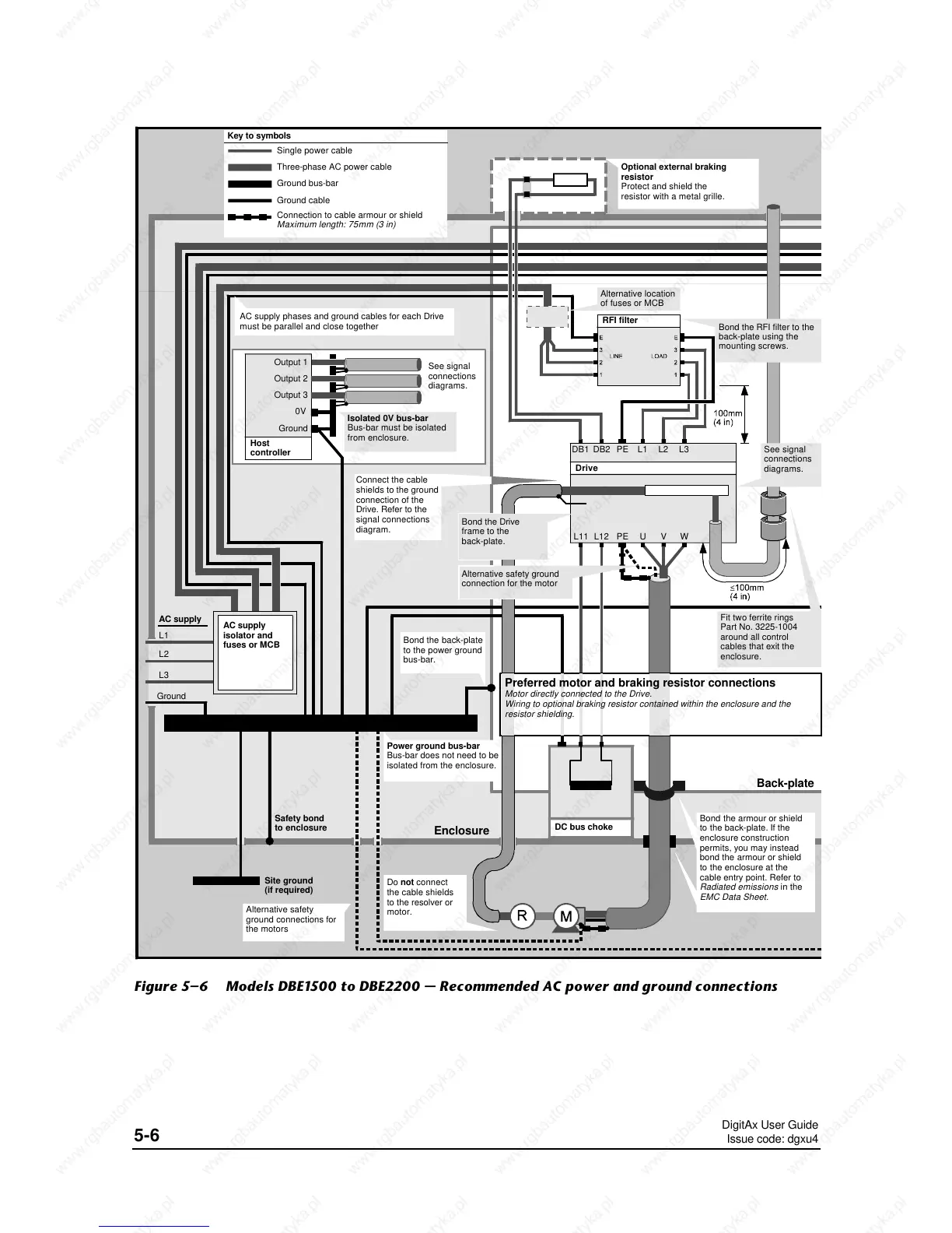
AC supply phases and ground cables for each Drive
must be parallel and close together
Output 1
Output 2
Output 3
Ground
Host
controller
See signal
connections
diagrams.
Isolated 0V bus-bar
Bus-bar must be isolated
from enclosure.
Power ground bus-bar
Bus-bar does not need to be
isolated from the enclosure.
AC supply
isolator and
fuses or MCB
AC supply
Ground
Safety bond
to enclosure
Site ground
(if required)
Key to symbols
Single power cable
Three-phase AC power cable
Ground bus-bar
Connection to cable armour or shield
Maximum length: 75mm (3 in)
RFI filter
L11 L12 PE U V W
Drive
DC bus choke
Ground cable
Bond the armour or shield
to the back-plate. If the
enclosure construction
permits, you may instead
bond the armour or shield
to the enclosure at the
cable entry point. Refer to
Radiated emissions
in the
EMC Data Sheet.
Bond the back-plate
to the power ground
bus-bar.
Bond the RFI filter to the
back-plate using the
mounting screws.
See signal
connections
diagrams.
Fit two ferrite rings
Part No. 3225-1004
around all control
cables that exit the
enclosure.
Back-plate
Enclosure
Alternative safety
ground connections for
the motors
Alternative location
of fuses or MCB
Bond the Drive
frame to the
back-plate.
Alternative safety ground
connection for the motor
Connect the cable
shields to the ground
connection of the
Drive. Refer to the
signal connections
diagram.
Do not connect
the cable shields
to the resolver or
motor.
Optional external braking
resistor
Protect and shield the
resistor with a metal grille.
Preferred motor and braking resistor connections
Motor directly connected to the Drive.
Wiring to optional braking resistor contained within the enclosure and the
resistor shielding.
Figure 5–6 Models DBE1500 to DBE2200 — Recommended AC power and ground connections
 Loading...