DigitAx User Guide
Issue code: dgxu4
5-10
Take the following precautions for external braking
resistors:
The braking resistor should be capable of
tolerating thermal shock; pulse rated resistors
are recommended.
Position the braking resistor so that heat
dissipated from it cannot affect the Drive.
Thermal-trip circuit for the
braking resistor
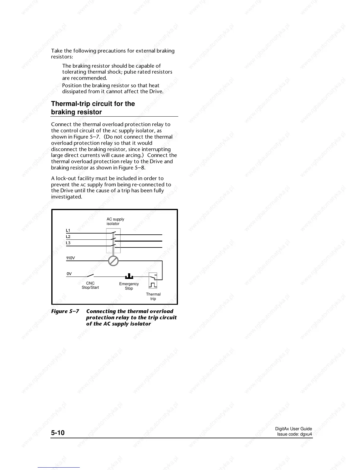
Connect the thermal overload protection relay to
the control circuit of the
AC supply isolator, as
shown in Figure 5–7. (Do not connect the thermal
overload protection relay so that it would
disconnect the braking resistor, since interrupting
large direct currents will cause arcing.) Connect the
thermal overload protection relay to the Drive and
braking resistor as shown in Figure 5–8.
A lock-out facility must be included in order to
prevent the
AC supply from being re-connected to
the Drive until the cause of a trip has been fully
investigated.
CNC
Stop/Start
Emergency
Stop
AC supply
isolator
Thermal
trip
Figure 5–7 Connecting the thermal overload
protection relay to the trip circuit
of the AC supply isolator
 Loading...