DigitAx User Guide
Issue code: dgxu4
5-16
Analog I/O
Digital I/O
Resolver
CON
B
CON
D
CON
C
CON
E
Serial
communications
Encoder
simulation
Encoder
backup
Figure 5–13 DBE1500, DBE2200 Layout of the
control signal connectors on the
front panel
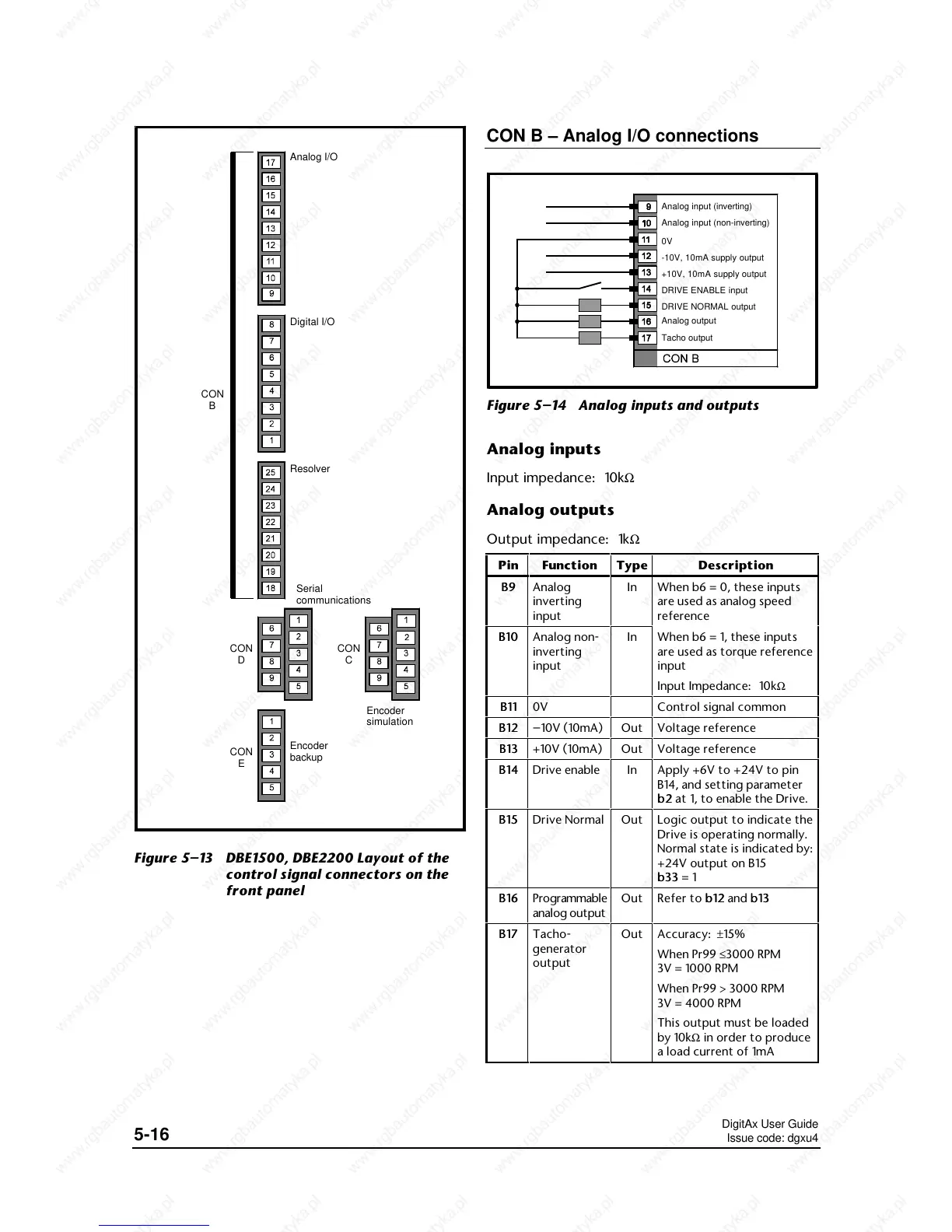
CON B – Analog I/O connections
Analog input (inverting)
Analog input (non-inverting)
-10V, 10mA supply output
+10V, 10mA supply output
DRIVE ENABLE input
0V
DRIVE NORMAL output
Analog output
Tacho output
Figure 5–14 Analog inputs and outputs
Analog inputs
Input impedance: 10kΩ
Analog outputs
Output impedance: 1kΩ
Pin
In When b6 = 0, these inputs
are used as analog speed
reference
B10B10
In When b6 = 1, these inputs
are used as torque reference
input
Input Impedance: 10kΩ
B11B11
Control signal common
B12B12 –
Out Voltage reference
B13B13
Out Voltage reference
B14B14
In Apply +6V to +24V to pin
B14, and setting parameter
b2b2 at 1, to enable the Drive.
B15B15
Out Logic output to indicate the
Drive is operating normally.
Normal state is indicated by:
+24V output on B15
b33 b33 = 1
B16B16
Out Refer to b12b12 and b13b13
B17B17
Out Accuracy: ±15%
When Pr99 ≤3000 RPM
3V = 1000 RPM
When Pr99 > 3000 RPM
3V = 4000 RPM
This output must be loaded
by 10kΩ in order to produce
a load current of 1mA
 Loading...