DigitAx User Guide
Issue code: dgxu4
5-18
Pin Function Type Description
B6B6 Programmable
input 0
In The function of this input is
selected using b18b18, b53b53 and
Pr27Pr27 as follows:
Zero speed
Hold
Shaft orientation input.
b18 Signal applied to B6 Function
0 logic 0 Not stop
1 X Stop
X logic 1 Stop
Pin Function Type Description
B7B7 Programmable
output 1
Out Refer to Pr30Pr30
B8B8 Programmable
output 0
Out Refer to Pr31Pr31
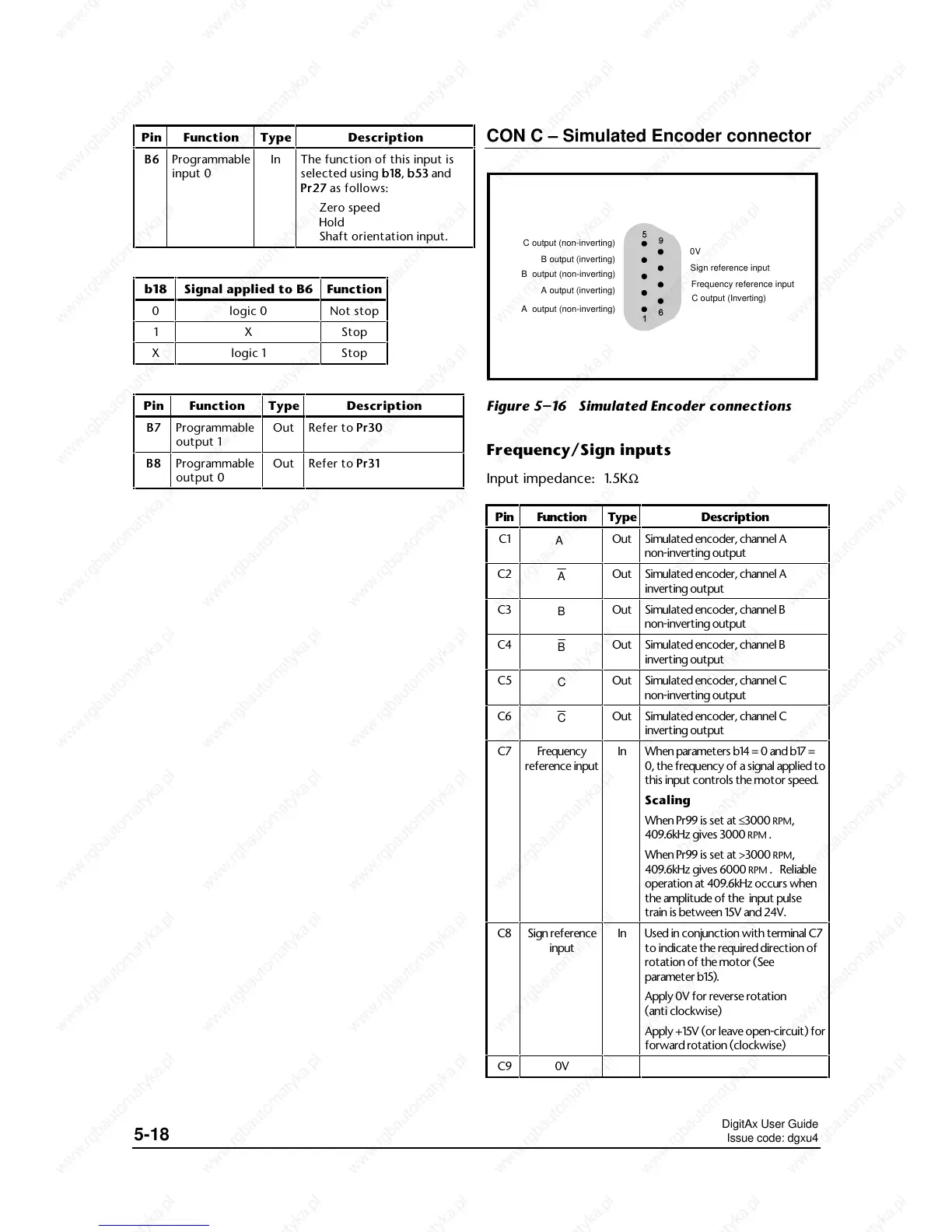
CON C – Simulated Encoder connector
A output (non-inverting)
A output (inverting)
B output (non-inverting)
B output (inverting)
C output (non-inverting)
C output (Inverting)
Frequency reference input
Sign reference input
0V
Figure 5–16 Simulated Encoder connections
Frequency/Sign inputs
Input impedance: 1.5KΩ
Pin
Type Description
C1
A
Out Simulated encoder, channel A
non-inverting output
C2
A
Out Simulated encoder, channel A
inverting output
C3
B
Out Simulated encoder, channel B
non-inverting output
C4
B
Out Simulated encoder, channel B
inverting output
C5
C
Out Simulated encoder, channel C
non-inverting output
C6
C
Out Simulated encoder, channel C
inverting output
C7
In When parameters b14 = 0 and b17 =
0, the frequency of a signal applied to
this input controls the motor speed.
Scaling
When Pr99 is set at ≤3000
RPM,
409.6kHz gives 3000
RPM .
When Pr99 is set at >3000
RPM,
409.6kHz gives 6000
RPM . Reliable
operation at 409.6kHz occurs when
the amplitude of the input pulse
train is between 15V and 24V.
C8
In Used in conjunction with terminal C7
to indicate the required direction of
rotation of the motor (See
parameter b15).
Apply 0V for reverse rotation
(anti clockwise)
Apply +15V (or leave open-circuit) for
forward rotation (clockwise)
C9
 Loading...