L1 L2 or N
GND
L1
L2 or N
Line
L1
L2 or N
Ground
Line
rigHT SiDE POWEr COnnECTiOn
LEFT SIDE POWER CONNECTION
L1
L2 or N
Ground
WiTH SingLE POLE THErMOSTaT
For Right hand side connection use same logic.
L1
L2 or N
Ground
WiTH DOUBLE POLE THErMOSTaT
For Left hand side connection use same logic
Load
Ground
!
NOTE: When control accessories are installed, use wiring diagram supplied with the accessory. Following are examples of wiring
diagrams with thermostat.
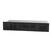
CONNECTING MULTIPLE LINEAR CONVECTORS TOGETHER
3
In keeping with our policy of continuous product improvement, we reserve the right to make changes without notice.
© 2011 Dimplex North America Limited
1367 Industrial Road Cambridge ON Canada N1R 7G8
1-888-346-7539 www.dimplex.com
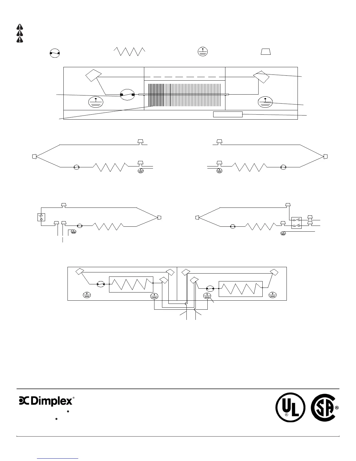
WIRING INSTRUCTIONS
CAUTION: Do not bypass or eliminate thermal cutout from the circuit.
CAUTION: Check tightness of all electrical connections and wire nuts.
CAUTION: Grounding connection is required. .
LEgEnD: Thermal cutout
Heating element
Wire nut connection Ground
Thermal cutout
Nameplate
Wire nut connection
Ground
Heating Element
FACTORY WIRING