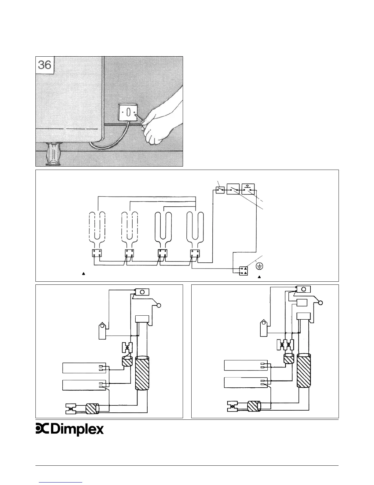
36. Ensuring the electricity supply is disconnected, connect the free end of
the mains cable to a suitable double-pole witch adjacent to the appliance
- reinstate the electricity supply.
NOTE: The double pole witch must have a contact separation at least
3mm in all poles.
Room Sensing Thermostat (CXLSN)
Models only
Thermostat Safety Cut-out
Charge Controller
Mains Supply
Terminal Block
& Earth Terminal
N
L
Site Connections
CXL12N/CXLS12N
CXL18N/CXLS18N
Heating Elements
CXL24N/CXLS24N
Circuit Diagram
Peak Circuit Diagram
CXL12N & 18N
CXLS12N & 18N
BROWN
BROWN
CUT-OUT
MAUVE
BLUEBLUE
BLUE
BROWN
MAUVE
BROWN
CONVECTOR
ELEMENT
CONVECTOR
ELEMENT
ELEMENT
SELECTOR
BLOCK
MAINS
BLOCK
‘L’
‘N’
SWITCH
NEON
AIR
SENSING
STAT
Peak Circuit Diagram
CXL24N
CXLS24N
BROWN
BROWN
CUT-OUT
MAUVE
BLUEBLUE
BLUE
BROWN
MAUVE
BROWN
CONVECTOR
ELEMENT
CONVECTOR
ELEMENT
ELEMENT
SELECTOR
BLOCK
MAINS
BLOCK
‘L’
SWITCH
NEON
AIR
SENSING
STAT
BROWN
BROWN
24
STAT
‘N’
© GDC Group Ltd. All rights reserved.
Material contained in this publication may not be reproduced in whole or in part, without prior permission in writing.
A division of the GDC Group Ltd, Millbrook House, Grange Drive, Hedge End, Southampton SO30 2DF
Dimplex UK Limited,
Millbrook House,
Grange Drive,
Hedge End,
Southampton, SO30 2DF.
Tel: 0845 600 5111
Fax: 01489 773 050
Web-site www.dimplex.co.uk
 Loading...