In keeping with our policy of continuous product improvement, we reserve the right to make changes without notice.
© 2011 Dimplex North America Limited
1367 Industrial Road Cambridge ON Canada N1R 7G8
1-888-346-7539 www.dimplex.com
3
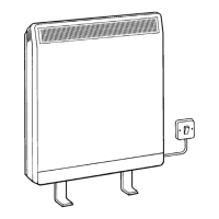
L1
L2 or N
L1
L2 or N
Line
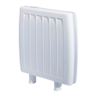
L1
L2 or N
Line
Right Side Power Connection Left Side Power Connection/
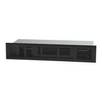
L1
L2 or N
Single Pole Thermostat
For right hand side connection use same logic.
L1
L2/N
Double Pole Thermostat
For Left hand side connection use same logic.
Load
!
NOTE: When control accessories are installed, use wiring diagram supplied with the accessory. Following are examples of wiring diagrams with thermostat.
Connecting Multiple Linear Convectors Together
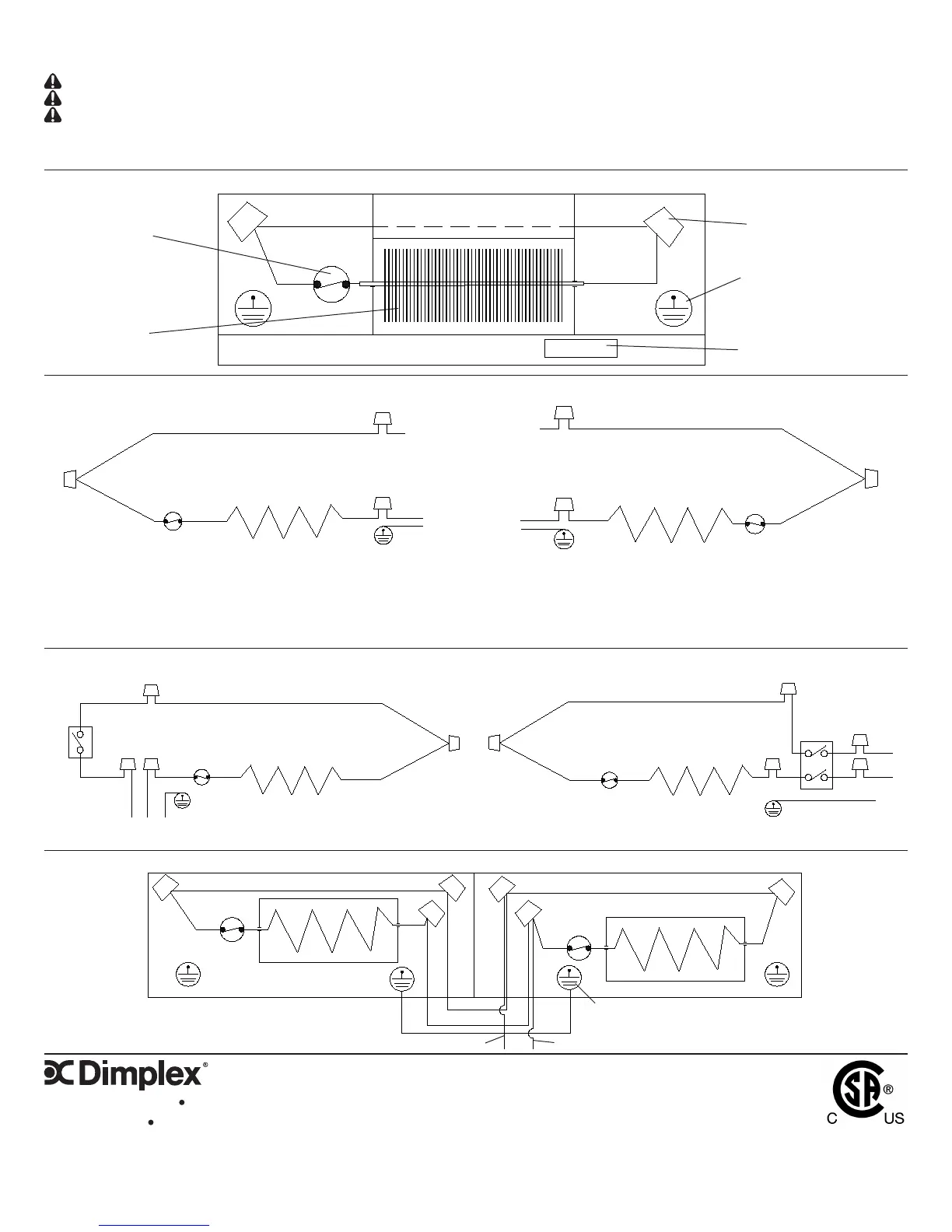
Nameplate
FACTORY WIRING
Wiring Instructions
CAUTION: Do not bypass or eliminate thermal cutout from the circuit.
CAUTION: Check tightness of all electrical connections and wire nuts.
CAUTION: Grounding connection is required.
Thermal cutout
Heating element
Wire nut connection
Ground
Ground
Ground
Ground
Ground
Ground