VENTILATION & DUCTING
Cupboard Ventilation - When the heater is installed in a cupboard,
two return grilles should be provided in the cupboard door or wall.
The top of the high level grille should be approximately 50mm
below the top of the cupboard and the bottom of the low level grille
approximately 25mm above the plenum top.
Return air grilles should be a minimum of 400mmx250mm. Grilles
must be positioned to return air from the heated areas.
Ducting will be required if the heater is positioned in a cupboard
and also in free standing installations if adjacent rooms are also to
be heated.
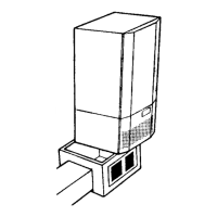
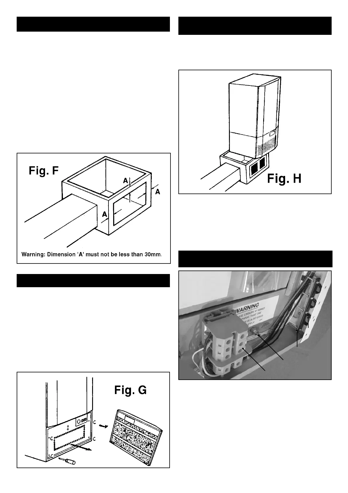
Holes to the required dimensions (to suit airducts used) should be
cut in the sides of the plenum chamber prior to siting. Holes should
not be cut closer than 30mm to either sides, top or bottom of the
plenum - see Fig F. The chamber can then be placed in position.
The ductwork can now be fi rmly attached to the plenum internally,
be means of ‘bent over’ fl anges or externally by pop rivets. Ensure
that all joints are sealed by 50mm wide tape.
INSPECTION BEFORE INSTALLATION
Having removed the heater from its packing inspect it for possible
damage caused in transit. Note - two sheets of mica insulation will
be found underneath the heater. Retain these in a safe place, see
Section 6. An inspection of the core bricks should also be made
at this stage.
Remove the fi lter panel by pulling the top end away from the heater,
and lift out of location hooks - see Fig G.
Remove the grille mesh by fi rst unscrewing the fi xing screws, then
spring out one end - the grille should now lift clear.
Check that all wiring connections are secure and that the fan rotates
freely.
INSTALLATION
1. Lift the heater onto the plenum and work it gently backwards
to its correct location, see Fig. H. Position the heater exactly over
the plenum with sides and rear fl ush to ensure stability. If fi tted in
a cupboard please ensure that the heater is facing the cupboard
door to allow for ease of access.
2. CONNECTION OF THE MAINS CABLE
Cable entry to the unit is at the bottom right hand corner when viewed
from the front. See Fig. I. Conductors are to be fed through bushings
and the clamping bar before being terminated in the terminal blocks
on the lower wiring panel. Several blanking plugs are provided for
any cable entry bushings that are not used.
Important - All mains supplies have to be installed with
independent isolators.
WARNING - This appliance must be earthed
Main element supplies can be provided from either single phase or
3 phase supplies.
If 3 phase is chosen, the switching circuit must use the red
phase.
An auxiliary or pilot circuit is also required, see Point 3. Control of
the fan operation by a time clock or thermostat is also an option.
Use wiring diagrams for more detail - Figs. A, B and C.
Important
Clarify if the day energy provided by the main heating element is
required. See Point 4.
Carry out the following instructions with care.
Bushing
Clamping Bar
Earth
Terminal Block
Fig. I
 Loading...