6. CORE ASSEMBLY - see Fig. T
NOTE: It is essential that the thermal insulation, especially
the moulded air passages, are not damaged during assembly.
Follow these instructions carefully.
Care must be taken to ensure that the bricks, when fi tted, do not
intrude into the space allowed for air passages around the core. Air
inlet and outlet holes in the bottom of the core must not be covered.
Avoid excess gaps in the core by placing the bricks as close as
possible during assembly.
Follow the instructions below and refer to Fig. T to ensure safe
installation.
Each layer uses 4 double sized bricks. Build the core a layer at a
time and include the elements at the appropriate position as shown
by the number indicated in Fig. T.
7. CONNECTING THE ELEMENTS
It is important that no part of the bare element wire is exposed or is
close to the brick. The elements are insulated with porcelain fi sh-
spine beads and can be pushed over the wire to ensure there are no
gaps. Locate each element tail in the appropriate groove and route it
round against the side and thread it through the ceramic bush in the
vertical terminal panel. Connect the end of the tail to the appropriate
terminal block. See Fig. O. Note: there is a maximum of two element
tails per terminal block. Check the wiring at this stage for electrical
continuity and insulation resistance. To ensure that the elements are
correctly tightened into the terminal block it is imperative to tighten
it again. This should be done at least three times.
iv) Remove the inner front panel by removing the securing screws.
This panel can now be pulled forward and then withdrawn by tilting
the top outwards and lifting.
v) Note carefully the correct location of the hole in the next layer
of insulation and remove. Check that the interior insulation has not
been disturbed in transit.
vi) Raise the plastic spacers separating the moulded air passages
slightly and remove packs containing elements and sealing strips.
Do not remove spacers until bricks have been built up to same level
as this helps to keep insulation in place - Fig. N.
Ensure both pieces of base insulation have not be disturbed
in transit.
Box
containing
Elements
Sealing
Strips
Spacers
Ensure base
insulation has
not moved during
transit.
Do not cover air inlet
and outlet holes.
vii) Inspect each element and the charge controller for damage
during transit.
The fi rst layer is constructed from 4 bricks running front to back and
the grooves on top as shown in Fig. S (a). Ensure these sit fi rmly
on the base and locate neatly between the moulded air ducts.
Handle the element with great care. Carefully locate each leg of
the element in a groove of the brick. The second layer can now
be positioned with the brick running from side to side as layer b.
(Except R15 Models - see Fig. T).
Refer to the table and sketch - see Fig. T and fi t the brick exactly as
shown. Element positions are indicated by the numbers.
IMPORTANT - Mica insulation sheets are provided to insulate
between phases. These must be fi tted between the brick layers at
the points indicated on the diagram. Additional labels are also fi tted
to the terminal panels of the heater.
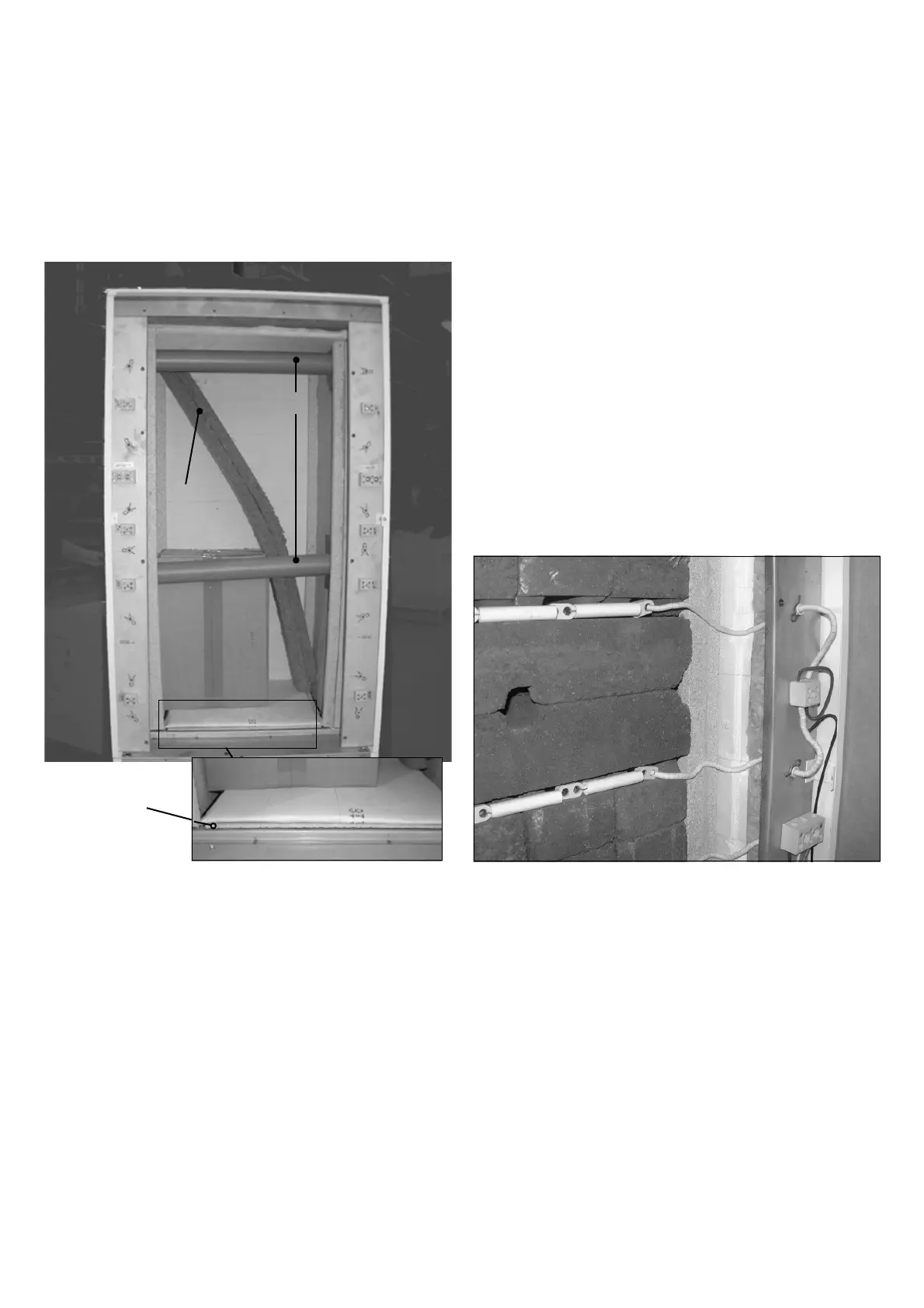
Fig. N
Fig. O
 Loading...