2
N506T 12-02
© 2002 Directed Electronics, Inc.
Adding a 506T to a DEI system that has an e
xternal shock sensor and reports separate zones on the shock sensor port
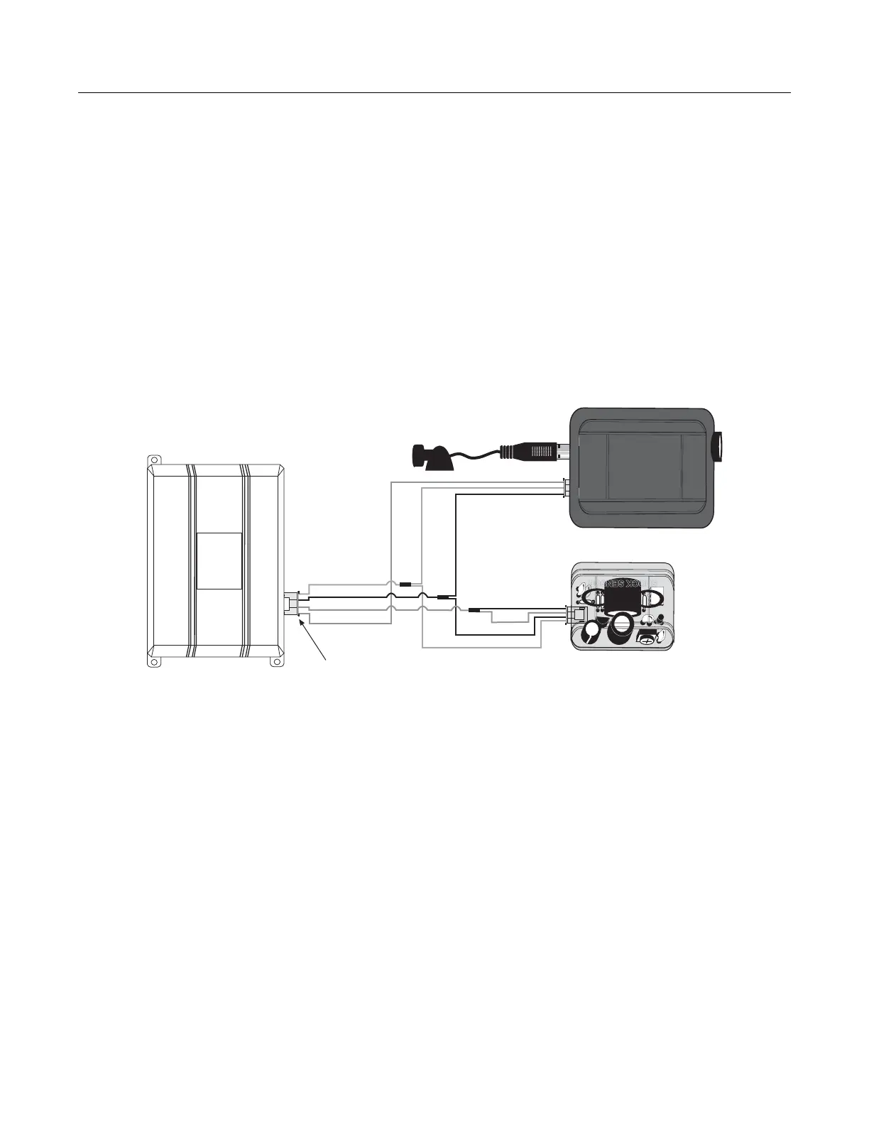
For DEI systems with separate Zone 2 and Zone 4 inputs (refer to the Table of Zones section of the alarm system’s
installation guide), refer to the configuration diagram below and follow these steps:
1. Plug the microphone into the 506T.
2. Plug the 3-wire audio sensor harness (with the blue, red, and black wires) into the 506T.
3. Plug the 4-wire main harness (with the red, black and two blue wires) into the shock sensor port of the alarm system.
4. Plug the remaining 4-wire shock sensor harness (with the green, blue, black and red wires) into the DEI shock sensor.
5. Adjust and test the audio sensor before mounting.
The shock sensor will report Zone 2, and the 506T will report Zone 4. (Refer to the Table of Zones section of the
alarm system’s installation guide.)