5
© 2011 Directed Electronics. All rights reserved.
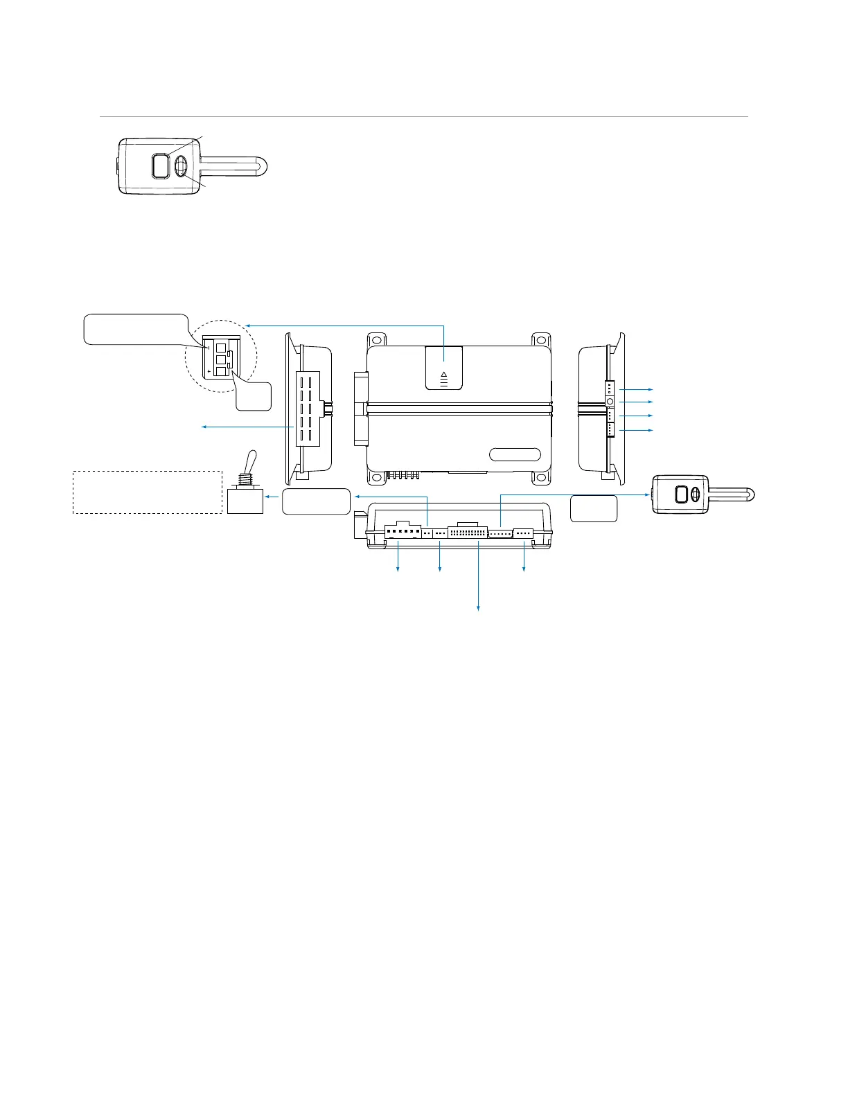
Wiring Diagram
Control button
Status LED
Control Center
Control Center
Control Center
Valet switch
LED
Control button
Status LED
Control Center
Control Center 6211T
Note:
Sensor ports 1 and 2 cannot support sensor 508D due to current limitations. These ports are also
constant power and ground connections.
5x04
Neutral Safety
Switch
1
10 9 8 7 6
12345
1
1 8
51
1 3
10
12
18
10
9
1
1 12
D2D Port (for external
Xpresskit interface module)
ON
IMPORTANT! Neutral Safety
switch must be plugged in
and in the ON position
RF Port
for IVU
Control Center
Thermistor/Temp Sensor
Sensor 1
Bitwriter/SmartStart Port
Door Lock
Port
Remote Start
10-pin Harness
Main 6-pin
Harness
10A FUSE
MINI ATM
RPN: 8540
LIGHT FLASH POLARITY
(10A (MAXIMUM) FUSE JUMPER)
Sensor 2
Aux/Shutdown/Trigger 24-pin Harness