EasyManuals Logo
Home>DISCO>Saw>DAD321

DISCO DAD321 User Manual

DISCO DAD321
20 pages
To Next Page IconTo Next Page
To Previous Page IconTo Previous Page
Page #10 background imageLoading...
Page #10 background image
Intro-6
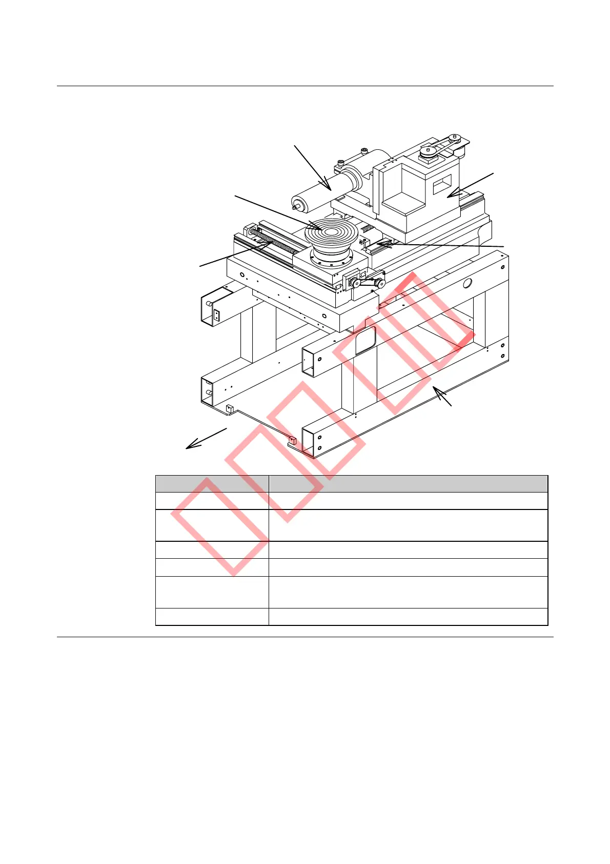
Axis Arrangement Diagram [321/351/361]
The diagram and the table below show axis arrangement, names and functions
of each axis.
X-axis
θ
-axis
(except 351)
Spindle axis
Z-axis
Y-axis
Main body frame
Front
Name Function
X-axis Moves the chuck table to the right and the left.
Y-axis Moves the spindle shaft and the microscope forward
and backward.
Z-axis Moves the spindle up and down.
θ -axis
Rotates the chuck table.
Spindle Shaft
Section
Rotates a blade at a high speed.
Main Body Frame Supports the machine main body.
Sample

Other manuals for DISCO DAD321

Questions and Answers:

Question and Answer IconNeed help?

Do you have a question about the DISCO DAD321 and is the answer not in the manual?

DISCO DAD321 Specifications

General IconGeneral
BrandDISCO
ModelDAD321
CategorySaw
LanguageEnglish

Related product manuals