Hardware Ins t a l l a t i o n G u i d e
PS-ADPSXXXXM Series
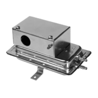
Air Differential Pressure Switch, Metal Enclosure
Figure 1: PS-ADPSXXXXM Series Air Differential Pressure Switches
Product Description
This document describes the hardware installation procedures for the
PS-ADPSXXXXM Series Air Differential Pressure Switches.
These devices are general-purpose airflow-proving switches designed
for HVAC and energy management applications. It may be used to
sense positive, negative, or differential air pressure.
The PS-ADPSXXXXM Series plated housing contains a diaphragm, a
calibration spring and a snap-acting SPDT switch. The enclosure
cover, guards against accidental contact with the live switch terminal
screws and the set point adjusting screw.
General Installation Requirements
For proper installation and subsequent operation of each device, pay
special attention to the following recommendations:
- Upon unpacking the product, inspect the contents of the carton for
shipping damages. Do not install damaged device.
- Avoid areas where corroding, deteriorating or explosive vapors,
fumes or gases may be present.
- Ensure that all equipment is installed according to local, regional,
and national regulations.
Take reasonable precautions to prevent electrostatic
discharges to the controller when installing, servicing or
operating the controller. Discharge accumulated static
electricity by touching one’s hand to a well-grounded object
before working with the controller.
Mounting Instructions
Select a mounting location which is free from vibration. The PS-
ADPSXXXXM Series pressure switch MUST be mounted with the
diaphragm in any vertical plane in order to obtain the lowest specified
operating set point. Avoid mounting with the sample line connections in
the “UP” position. Surface mount via the two 3/16” diameter holes in
the integral mounting bracket. The mounting holes are 3 7/8” apart.