Field Adjustment
For models PS-ADPS12WCMAX / MAB
The adjustment range of these models is 0.05 ±.02" w.c. to 12.0" w.c.
To adjust the set point:
1. Turn the adjusting screw counterclockwise until motion has
stopped.
2. Next, turn the adjusting screw 4 complete turns in a clockwise
direction to engage the spring. From this point, the next ten turns
will be used for the actual calibration. Each full turn represents
approximately 1.2" w.c.
To properly calibrate an air flow switch, a digital
manometer or other measuring device should be used to
confirm the actual set point.
For models PS-ADPS02WCMAX / MAB
The adjustment range of these models is 0.05 ±.02" w.c. to 2.0" w.c.
To adjust the set point:
1. Turn the adjusting screw counterclockwise until motion has
stopped.
2. Next, turn the adjusting screw 4 complete turns in a clockwise
direction to engage the spring. From this point, the next ten turns
will be used for the actual calibration. Each full turn represents
approximately 0.2" w.c.
To properly calibrate an air flow switch, a digital
manometer or other measuring device should be used to
confirm the actual set point.
For models PS-ADPS12WCMMX / MMB
The adjustment range of these models is 0.4" ± 0.02" w.c. to 12.0" w.c.
To adjust the set point:
1. Turn the adjusting screw counterclockwise until motion has
stopped.
2. Next, turn the adjusting screw four complete turns in a clockwise
direction to engage the spring. From this point, the next ten turns
will be used for the actual calibration. Each full turn represents
approximately 1.16" w.c.
To properly calibrate an air flow switch, a digital
manometer or other measuring device should be used to
confirm the actual set point.
Air Sampling Connection
PS-ADPS12WCMAX, PS-ADPS02WCMAX and PS-ADPS12WCMMX
models are designed to accept firm-wall sample lines of .25" OD tubing
by means of ferrule and nut compression connections.
PS-ADPS12WCMAB, PS-ADPS02WCMAB and PS-ADPS12WCMMB
models are designed to accept slip-on flexible lines of .25" OD tubing
by means of adapters with barbed fittings.
- For sample lines of up to 10 feet, .25" OD tubing is acceptable.
- For lines up to 20 feet, use .25" ID tubing.
- For lines up to 60 feet, use .5" ID tubing.
1. Locate the sampling probe a minimum of 1.5 duct diameters
downstream from the air source.
2. Install the sampling probe as close to the center of the airstream as
possible.
3. Identify the high pressure inlet (H) and the low pressure inlet (L).
4. Select one of the five application options listed below and connect
the sample lines as recommended.
Positive Pressure Only:
Connect the sample line to inlet H; inlet L remains open to the
atmosphere.
Negative Pressure Only:
Connect the sample line to inlet L; inlet H remains open to the
atmosphere.
Two Negative Samples:
Connect the higher negative sample to inlet L.
Connect the lower negative sample to inlet H.
Two Positive Samples:
Connect the higher positive sample to inlet H.
Connect the lower positive sample to inlet L.
One Positive and One Negative Sample:
Connect the positive sample to inlet H.
Connect the negative sample to inlet L.
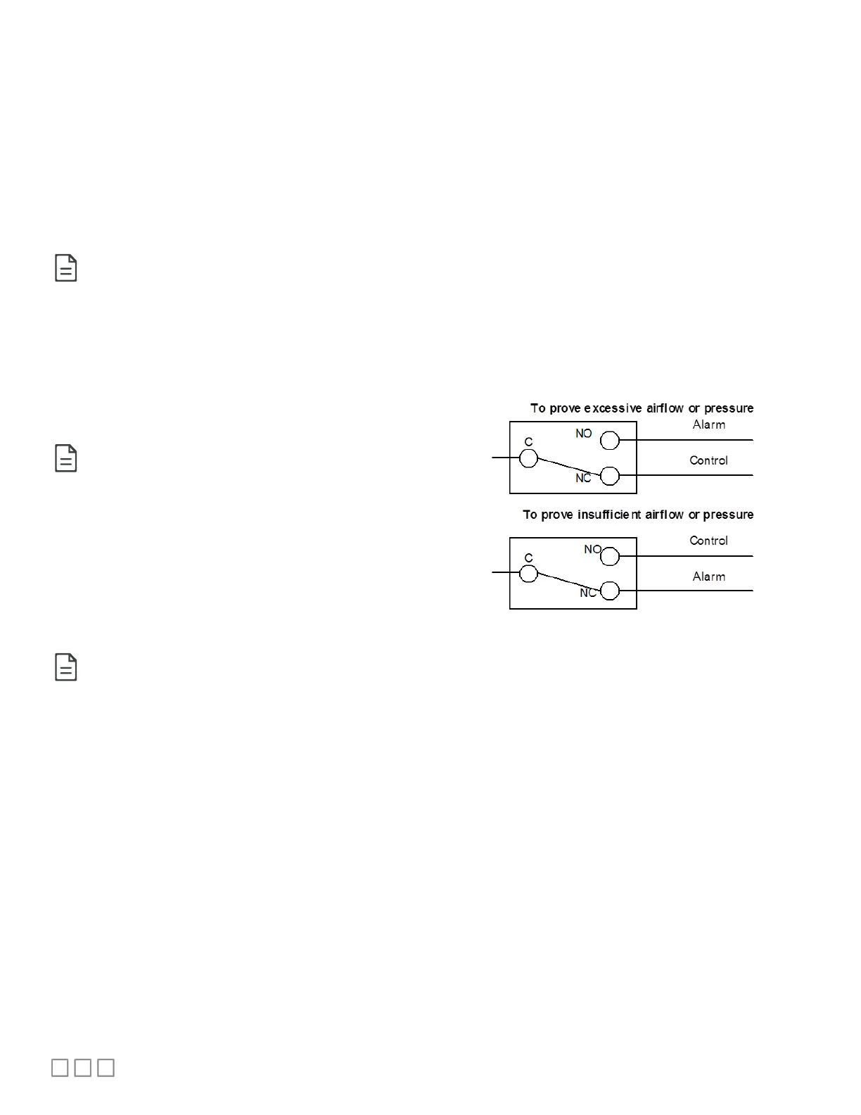
Wiring Diagram
Alarm or Control
Figure 2.
 Loading...