dIXEL
Operating and Instructions Manual
1592006100
1592006100 XB570L GB r1.0 04.11.2004.doc XB570L 1/6
XB570L
BLAST CHILLER - QUICK CHILL AND HOLD FUNCTION
Contents
1. General warning_______________________________________ 1
2. General Features ______________________________________ 1
3. Mounting & Installation__________________________________ 1
4. Electrical Connections __________________________________ 1
5. Connections __________________________________________ 1
6. Frontal panel _________________________________________ 1
7. Front Panel Commands _________________________________ 2
8. How To Select A Cycle. _________________________________ 2
9. How To Start The Selected Cycle._________________________ 2
10. How to temporarily stop the running cycle. __________________ 2
11. How to definitively stop the cycle. _________________________ 2
12. How To Modify The Set Point Of The Hold Mode. _____________ 2
13. How to start a manual defrost. ____________________________ 2
14. How A Cycle Is Done. __________________________________ 2
15. Function And Parameter Programming Menu ________________ 3
16. Accessing “Pr2” and SECURITY CODE input ________________ 4
17. List of parameters______________________________________ 4
18. Printer management____________________________________ 5
19. IV configurable relay. ___________________________________ 5
20. Digital configurable input.________________________________ 5
21. ALARM SIGNALS _____________________________________ 5
22. Technical data ________________________________________ 6
23. Standard Value of the cycles._____________________________ 6
24. Standard Values of the parameters.________________________ 6
1. General warning
1.1
PLEASE READ BEFORE USING THIS MANUAL
• This manual is part of the product and should be kept near the
instrument for easy and quick reference.
• The instrument shall not be used for purposes different from those
described hereunder. It cannot be used as a safety device.
• Check the application limits before proceeding.
1.2
SAFETY PRECAUTIONS
• Check the supply voltage is correct before connecting the instrument.
• Do not expose to water or moisture: use the controller only within the
operating limits avoiding sudden temperature changes with high
atmospheric humidity to prevent formation of condensation
• Warning: disconnect all electrical connections before any kind of
maintenance.
• The instrument must not be opened.
• In case of failure or faulty operation send the instrument back to the
distributor or to “Dixell s.r.l.” (see address) with a detailed description of
the fault.
• Consider the maximum current which can be applied to each relay (see
Technical Data).
Ensure that the wires for probes, loads and the power supply are separated
and far enough from each other, without crossing or intertwining.
• Fit the probe where it is not accessible by the end user.
• In case of applications in industrial environments, the use of mains filters
(our mod. FT1) in parallel with inductive loads could be useful.
2. General Features
The series XB has been created for fast chilling or freezing goods according
to international food safety standards.
There are FOUR types of cycles:
• The CYCLES: Cy1, Cy2, Cy3, Cy4 are pre-set according to the most
common cycles used in food - safety applications; the user can select
one of them according to his own requirements and modify it as he
wants.
• Any cycle can be manually terminated before the normal.
• Any cycle can use the third probe like an “insert probe”, it measures the
internal temperature of the product.
• During the Cycle there are no defrosts and the fans are always on, a
defrost cycle can be done before any freezing cycle.
• The cycle is divided up to 3 phases completely configurable by the user.
• Each instrument is provided with an output for remote display XR REP,
which shows the temperature of cabinets or goods.
• The XB570L controller is provided with internal real time clock and can
be connected to the XB05PR printer. This means that a report, which
includes all the main features of cycle, can be printed: start and end of
the cycle, length of the cycle, logging of the temperature of the cabinet
and goods.
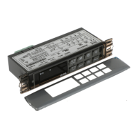
3. Mounting & Installation
Model XB570L is a controller panel mounted, hole dims 150x31 mm, and
fixed with the screws. The ambient working temperature range should be
between 0÷60°C. Avoid locations subject to heavy vibration, corrosive gases
or excessive dirt. The same applies to the probes. Ensure ventilation around
the instrument.
4. Electrical Connections
The instruments are provided with a screw terminal block to connect cables
with a cross section up to 2,5 mm
2
. Before connecting cables make sure the
power supply complies with the instrument’s requirements. Separate the
input connection cables from the power supply cables, from the outputs and
the power connections. Do not exceed the maximum current allowed on
each relay, in case of heavier loads use a suitable external relay.
4.1 PROBES CONNECTION
The probes shall be mounted with the bulb upwards to prevent damages due
to casual liquid infiltration. It is recommended to place the thermostat probe
away from air streams to correctly measure the average room temperature.
Place the defrost termination probe among the evaporator fins in the coldest
place, where most ice is formed, far from heaters and from the warmest
place during defrost, to prevent premature defrost termination.
5. Connections
Digital inp.
Evap.
Insert
Room
XB570L
Def.
Alarm/
AUX Fan
12A
250Vac
MAX
20A
8A
250Vac
8A
250Vac
Supply
230Vac
Comp
8A
250Vac
1913 14 15 16125678910111 2 3 4 17 18
6. Frontal panel
Aux
1 2
3 4
6.1 MEANING OF THE LEDS’
A series of light points on the front panels is used to monitor the loads
controlled by the instrument. Each LED function is described in the following
table.
LED MODE ACTION
ON - Compressor enabled
Flashing
- Programming Phase (flashing with LED )
- Anti-short cycle delay enabled
ON - Fans enabled
Flashing
- Programming Phase (flashing with LED )
- Activation delay active
ON - Defrost active
Flashing - Drip time active
ON - Freezing cycle or hold mode active
Flashing - Instrument temporarily stop
ON - Alarm signalling
- In “Pr2” indicates the parameter is also present
in “Pr1”
AUX ON - IV relay enabled