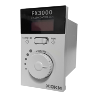
FX3000 manual
DKM DIGITAL SPEED TORQUE CONTROLLER
We appreciate you for purchasing products of
DKM Motor co., Ltd. Before using the product you have
purchased, check to make sure that it is exactly
what you ordered. Then, please use it following the
instructions below.
DKM Motor Co., Ltd.
Head Office / Factory
4F., Incheon Techpia Na-Bldg.,
Geobukro 17, Seo-gu, Incheon, Korea
Tel. +82.32.574.7788 Fax. +82.32.578.7787
www.dkmmotor.com
Head Office / Factory
4F., Incheon Techpia Na-Bldg.,
Geobukro 17, Seo-gu, Incheon, Korea
Tel. +82.32.574.7788 Fax. +82.32.578.7787
Operation/Parameter Setting Procedure
Display/ Setting
Specifications
CONTROLLER CODING SYSTEM
BEFORE USE
■ Check specifications which you ordered such as voltage,
output and so on.
■ Make sure a motor item whether the motor can be applicable with
DSKM controller.
■ Avoid the place in vibration, deep Impact, lots of dusty, inflammable
gas and corrosive gas.
■ Use ambient temperature(-10 ℃ ~ 40 ℃) and ambient humidity
(85% maximum and avoid direct sunlight, moisture and greasy place.
■ Install motor and controller as closely as possible. (within 2m)
■ Possible to control speed and torque.
■ Possible to control the speed and torque of the motor simply by
connecting motor and control unit with connector and inputting the
AC terminal to the power source.
■ Display the current rotation speed(r/min) and torque(%).
■ Possible to control speed and torque easily with the front panel dial.
■ Possible to operate various functions by setting the parameter.
■ Entire Transition Diagram
■ Operation setting procedure
After wiring, set as follows.
Display lights up(Rotation speed)
Decrease
in speed
Increase
in speed
MOTOR MOTOR
■ Parameter setting procedure
After wiring, set as follows.
※ Caution
Please change rotation direction after the motor
completely stops.
RPM changes if turn the dial.
If turning the dial slowly,
RPM increases/decreases by 1r/min.
If turning the dial quickly, the speed
variation becomes large.
Setting data will change automatically
after 2 seconds.
If the power turns on again,
it operates with the final setting value.
※ Please refer to ‘CW/CCW signal connection’ in the
manual if operating RUN/STOP extemally.
※Speed Control P, I gain
- Parameter to determine the responsibility of speed control.
- Vibration and hunting phenomenon occurs if the value is too large.
■ Initial setting mode is speed control. Please change ‘0’(speed mode) to ‘1’
(torque motor) after selecting parameter ‘Pr04’(control mode) if using torque motor.
Regarding changing method, please refer to ‘Parameter setting procedure’ and
‘Display/Setting’ in the manual.
FX3000 006 S
003: 3W
006: 6W
010: 10W
015: 15W
020: 20W
025: 25W
030: 30W
040: 40W
060: 60W
090: 90W
120: 120W
180: 180W
S:
Speed Motor
T:
Torque Motor
Controller Model TYPEOUTPUT
Model Name
FX3000-□□
Rated Voltage 1Ø AC 220~240V 50/60Hz ±10 %
Allowable Current Below 6 A
Control Function Speed Control, Torque Control
Control System Phase Control
Setting Range
Speed
Control
50Hz : 90~1400r/min
60Hz : 90~1700r/min
Torque
Control
0 ~ 100 %
Speed Setting Setting by Volume
Speed Variation ±5%(Standard Value)
Motor Output 3W~180W
Ambient Temperature -10C°~ 55C°
Ambient Humidity 35 ~ 85%RH (Without condensation)
Insulation Resistance
Over DC 500V 100MΩ
(between power supply and external terminal)
Dielectric Strength
AC 1500V 1minute
(between power supply and external terminal)
Parameter
Function Range
Standard
Value
Remark
NO.
Display
1 Pr01
Acceleration
Time
0~15.0
0.1
Time(second) to reach
the set speed
2 Pr02
Rotation
Direction
0, 1 0
0 : Clockwise
1 : Counterclockwise
3 Pr03 Gear Ratio 1~999 1.0
Input gear ratio
4 Pr04
Control
Mode
0, 1 0
0: Speed Control
1: Torque Control
5 Pr05 P Gain 0~255 100
6 Pr06 I Gain 0~255 50
7
Pr07
Parameter
Reset
- 0
Reset when pressing and
holding the SET button
SF PrSF
Software
Version
- -
Display the
software version
■ Parameter Contents
① Input AC power① Input AC power(Terminal CN1 #1, #2)
Display lights up(Rotation speed)
Turn the dial and choose the parameter
number which user wants to (Pr01~Pr07)
Press the dial(SET button) to enter
the parameter data.
Enter into the parameter mode as pressing the
MODE button while motor is stop condition.
(STAND-BY)
Motor operates if the switch is
RUN position
Motor stops if the switch is
STOP position
“Pr01” appear at display
(Parameter mode)
② Select parameter mode
② Operation switch→RUN
③ Operation switch→STOP
④ Rotation direction setting
⑤ Rotation speed setting
③ Parameter Data
④ Change Parameter Data
MODE Button
CW/CCW Switch
Clockwise
at ‘FWD’
Counter Clockwise
at ‘REV’
RPM DISPLAY
CW/CCW Switch
ENTER
PUSH
(Briefly)
DATA flickers and switches to changeable
status if pressing and holing the dial
(SET button) during 2 sec.
Data value will be changed and possible to
set the desired value if the dial is rotated
toward CW/CCW.
Data stop blinking and finish the setting when
pressing and holing the dial(SET button)
for 2 sec.
‘0’ output at display
(RPM)
(operation mode)
Press the MODE
button to enter the
operation mode.
Speed or Torque setting
with the dial
DIAL
Mode Button
Mode Button
⑤ Operation Mode
MODE Button
CHANGE
CHANGE
PUSH
(Hold-2sec.)
PUSH
(Hold-2sec.)
COMPLETE
CW/CCW
(Roration)
RPM display
Parameter PR01 PR01
PRSF PR07
SAFETY INFORMATION
SPECIAL FEATURES
!
!
!
Alerts declared in the manual are classified to Danger,
Warning and Caution by their criticality
There is a danger of occurred shock in the input/output terminals so please
never let your body or conductive substance is touched.
1. Do not put around the explosive atmosphere, gas to be burnt,
corrosive air, the location to be wet and combustibles.
If not, there will be the electric shock and the fire.
2. Installation, connection, operation, maintenance and diagnostic
operation should be carried out by the person who has expertise.
3. Use the product after turning off the power.
It may cause an electric shock.
4. The power cable and the lead wire should not be bent, pulled and
inserted by force. If not, the electric shock and the fire may occur.
5. In case of the motor and controlling unit are attached to the machine,
never touch with hand or connect with the earth. If not, the electric
shock may take place.
6. Within the 30 seconds after the power off, do not touch the output
terminal of the controlling unit. If not, the electric shock may occur
because of the residual volts.
DANGER
!
DANGER
WARNING
!
WARNING
CAUTION
!
CAUTION
DANGER indicates imminently hazardous situation which,
if not avoided, will result in death or serious injury.
WARNING indicates a potentially hazardous situation which,
if not avoided, could result in death or serious injury.
CAUTION indicates a potentially hazardous situation which,
if not avoided, may result in minor or moderate injury.
The motor and the controlling unit should be used only by the
designated compounding. If not, the fire may occur.
Do not operate with the wet hands. The electric shock may occur.
In case of moving, do not catch the output shaft, connecting part or
the lead wire. There may be the injury by the drop.
The motor should be used after it is fixed tightly. If not, the injury
and/or the damage of the unit may occur.
Do not touch the rotating part (output shaft, cooling fan) in running.
It could be cause of injury.
If there are abnormal cases, turn off the power at once. If not, there
will be the electric shock, injury and the damage.
Do not touch the motor for a while, if the motor’s surface temperature
exceeds 90℃.
Be sure to set the switch STOP before connecting to the power.
Make sure to check the rotating direction before connecting the
machine. If not, the injury and/or the damage of the unit may occur.
Use products only according to the specification of motor and
controlling unit. If not, there will be dangerous fire, electric shock,
injury and/or damage of the unit.
Make sure to install the overload device because the protection device
is not attached to the motor. It is desirable to install other protection
devices other than overload protection device to prevent fire.
1.
2.
3.
4.
5.
6.
7.
8.
9.
10.
11.