PAGE2OF2 REV. B 05/01 FILE # DS0026 DOC#PT-100-DS
1. Allow PT-100 to warm up for 5 minutes.
2. Depress the reset toggle momentarily.
3. Zero the display by alternatingly turning the zero knob
andmomentarily pressingthe resettoggleuntil thedis-
play reads 00.0.
4. Press the R-cal button on the back of the unit. Press
the reset toggle to zero the display. Repeat this pro-
cess several times to assure a repeatable value. The
display value (R-cal # X .005 = tolerance
R-cal # plus & minus tolerance = range)
should be within .5% of the value recorded on the bot-
tom of the unit.
EXAMPLE: R-cal = 81.0
81.0 X .005 = .40
80.6 to 81.4 = range
5. If anyof theproceduresin steps 2-4donot producethe
expected results, the unit should be returned to DMC
forrepair andrecalibration.
6. SERVICE
Repairand calibration servicesfor thePT-100 WireCrimp
Pull Tester is available from Daniels Manufacturing Corpora-
tion. Spare parts are also available.
Shoulditbe necessary to returnthe unit forservice, please
ship tothe address onthis datasheet, freightprepaid. Enclose
aletter, or purchaseorderwith company name,address, phone
number, the individual to be contacted and the reason for re-
turn.
COPYRIGHT©2001 ALLRIGHTSRESERVED
NOTE: This option is made of heavier
duty material and is useful specifically
for testing ring terminals. It also offers
a universal "V" groove for testing non-
standard terminal sizes.
the amount of force exerted on the crimp. As the force is
increased the display will continue to update the reading until
the force is no longer increasing. (Usually this is the point at
which the crimp is pulled loose, or the wire breaks.)
Upon completion of the test, release the wire and press
the reset button on the display prior to the next test.
Best results are obtained with the PT-100 using a slow,
consistent motion when pulling the lever. A quick, or hesitant
motion can cause the wire to slip within the self tightening
cams and the terminal also may become unseated within the
slot.
4.CHANGING TERMINALGRIPS
CAUTION: The PT-100utilizes aprecision loadcell for
its force measurement. Care must be exercised when
changing grips not to create excessive side load on the
load cell sensor.
To change or replace the terminal grip complete the fol-
lowing steps in sequence.
1. Toprovide moreroom to workraise the rackand pinion
lever arm assembly as high as possible. Loosen the
large black knob on the left hand side of the assembly,
raise the assembly and retighten the knob.
2. Using a 9/64 in. hex key and an 11/32 in. open end
wrench, loosen and remove the 8-32 locking hex nut
from the bottom of the sensor assembly.
3. Remove the 8-32 x 1-1/2 in. screw, slip washer, termi-
nal grip and spacer from the sensor.
4. When installing the optional ring terminal grip, the re-
cessed center hole must face up for proper operation.
5. Reassemble in this order: Install slip washer on screw,
followed by the terminal grip, and spacer. Insert the
screw with this assembly through the hole in the sen-
sor.
6. Install 8-32 locking hex nut.
7. Using the hex key and open end wrench, tighten until
some effort is required to rotate terminal grip. This is
necessary to avoid play between the terminal grip and
the sensor.
8. Lower the rack and pinion lever arm assembly to its
operating level and tighten knob to secure.
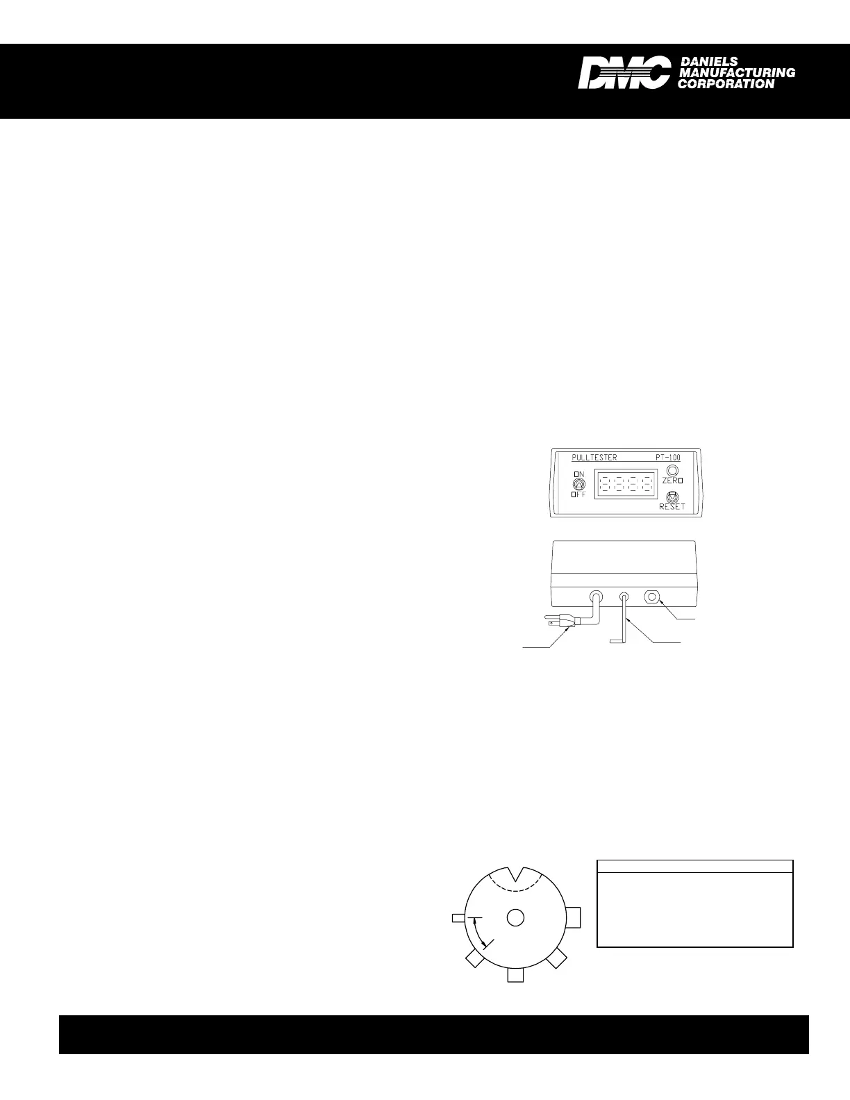
5. FUNCTIONALCHECK
The PT-100 Wire Crimp Pull Tester is factory calibrated
with equipmenttraceable tothe NationalInstituteof Standards
and Technology (NIST). We recommend recalibrating the unit
at intervals not to exceed one year in duration.
The funtional check is executed using the R-cal switch
built into the unit . The R-cal switch is located on the rear of
the unit, and its R-cal value is on the sticker applied to the
bottom of the unit.
A functional check can be performed at any time:
OPTIONAL RING TERMINAL GRIP
DATASHEET
DANIELS MANUFACTURING CORP., 526 THORPE ROAD,ORLANDO, FL 32824, USA
PHONE (407) 855-6161 • FAX (407)855-6884 • WWW.DMCTOOLS.COM • E-MAIL: DMC@DMCTOOLS.COM
RING POSITION
1 Slot .200" to .03" @ .250" Depth
2 3/8" Dia. x .250" Pin
3 5/16" Dia. x .250" Pin
4 1/4" Dia. x .250" Pin
5 3/16" Dia. x .250" Pin
6 1/8" Dia. x .250" Pin
1
2
3
4
5
6
45° TYP.
LEADTOLOAD
CELL
R-cal
POWER
(115 VAC)
FRONTVIEW
REARVIEW
 Loading...