EasyManua.ls Logo

DMC Alphatron PT-100 - User Manual

DMC Alphatron PT-100
2 pages
Print Icon
To Next Page IconTo Next Page
Loading...
PAGE1OF2
PT-100
WIRE CRIMP PULL TESTER
COPYRIGHT©2001 ALLRIGHTSRESERVED REV. B 05/01 FILE # DS0026 DOC # PT-100-DS
1
2
3
4
5
6
7
15
14
13
12
11
10
98
SLOT DIMENSION
No.
1
2
3
4
5
6
7
8
Size (in.)
.031
.250
.047
.236
.063
.218
.080
.203
No.
9
10
11
12
13
14
15
Size (in.)
.094
.188
.110
.172
.125
.158
.141
MAX
MIN
Dual Cam Action Grips
Upper Grips from 0 to .250" Diameter
Wire
UPPER GRIP
"Quick Grip"
LOWER GRIP
Standard Terminal Grip
1. SAFETY
The Alphatron PT-100 Wire Crimp Pull Tester is a force
measurementdevice,andoperatorsshouldwearsafetyglasses
for eye protection because foreign objects can be thrownfrom
the piece under test.
Topreventfireandshock hazard, do not expose thisequip-
ment to moisture. Always unplug the AC line cord prior to ser-
vicing.
Do notexceed the ratedforce capacity (100lb., 45 kg.)of
the PT-100. The unit may be damaged, and the operator or
others in the immediate vicinity injured under extreme force
conditions.
2. SETUP
The Alphatron PT-100 is shipped from the DMC factory
assembled, calibrated, and tested. For best results, users
should familiarize themselves with the setup and operation of
the unit before placing it in service.
To operate, set the PT-100 on a flat, level surface in an
upright position. To prevent damage to the force sensing de-
vice, handle the unit by the main support post and base only.
Threemounting holesin thebaseare providedto permanently
bolt it in position, if desired.
Setthemeteralongsidethebase. Be careful to avoidstrain
on the cord between the meter and the load cell. The meter
has folding legs to permit the operator to adjust the viewing
angle.
3. OPERATION
With the switch on the front of the meter turned off, plug
the PT-100 intoa 115VAC or appropriate outlet. Turn it on and
the display will light up to indicate that the unit is operational.
Allow 5 minutes warm-up prior to operating the unit. Zero the
display byalternatively turningthe zeroknob andmomentarily
pressing the reset toggle. The display should read 00.0. It is
important to push the reset toggle before taking the next read-
ing.
To select the correct "lower grip" slot for the wire/terminal
lead to be tested proceed as follows:
Rotate the grip to find the slot in which the lead wire fits
best. Select the slot that is the same width as the wire diam-
eter or one increment larger.
Insert the wire into the slot with the terminal down and
clear of the bottom surface of the "lower grip". Next, pass the
wire between the knurled upper grip cams and raise the lever
arm on the left hand grip to the "min" position to hold the wire
in place. Check to be sure that when you pull down on the
operating lever, the wire will be pulled as nearly vertical as
possible. Adjust the "lower grip" as necessary to make this
alignment.
Pull the operating lever downward in a slow and consis-
tent motion while holding the "upper grip" lever until its self
tightening action takes over. The indicator will begin to display
PT-100
DATASHEET
DANIELS MANUFACTURING CORP., 526 THORPE ROAD,ORLANDO, FL 32824, USA
PHONE (407) 855-6161 FAX (407)855-6884 WWW.DMCTOOLS.COM E-MAIL: DMC@DMCTOOLS.COM
DONOTEXCEEDTHE
RATEDFORCEOF100LB
BASE
METER
KNURLEDSURFACE ON O.D.
Question and Answer IconNeed help?

Do you have a question about the DMC Alphatron PT-100 and is the answer not in the manual?

Summary

Safety Precautions

Setup and Initial Configuration

Operation of the Wire Crimp Pull Tester

Upper Grip Mechanism

Details the dual cam action grips for the upper part.

Lower Grip Selection and Use

Describes the standard terminal grip with slot dimensions.

Changing Terminal Grips

Functional Check Procedure

Service and Support

Optional Ring Terminal Grip

Details an optional grip for testing ring terminals.

Overview

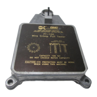
The Daniels Manufacturing Corporation (DMC) PT-100 Wire Crimp Pull Tester is a specialized force measurement device designed to evaluate the strength of wire crimps. It is crucial for operators to wear safety glasses during operation to protect against potential foreign objects. The device has a rated force capacity of 100 lb (45 kg), which must not be exceeded to prevent damage to the unit and potential injury to the operator or others nearby. To ensure safety and prevent fire or shock hazards, the unit should not be exposed to moisture, and the AC line cord must be unplugged prior to servicing.

Function Description:

The PT-100 measures the amount of force required to pull a wire crimp loose or break the wire. It provides a digital display that updates in real-time as force is applied. The device is shipped from the DMC factory fully assembled, calibrated, and tested, ensuring immediate usability. For optimal performance, the unit should be placed on a flat, level surface in an upright position. Handling the unit by its main support post and base only is recommended to prevent damage to the force sensing device. The base includes three mounting holes for permanent installation if desired. The accompanying meter features folding legs, allowing the operator to adjust the viewing angle.

Important Technical Specifications:

  • Rated Force Capacity: 100 lb (45 kg).
  • Display: Digital, showing force readings.
  • Power: 115VAC (or appropriate outlet).
  • Grip Types:
    • Upper Grip ("Quick Grip"): Dual cam action grips, accommodating wire diameters from 0 to .250 inches.
    • Lower Grip (Standard Terminal Grip): Features 15 slots with varying dimensions for different wire sizes.
      • Slot 1: .031 in.
      • Slot 2: .250 in.
      • Slot 3: .047 in.
      • Slot 4: .236 in.
      • Slot 5: .063 in.
      • Slot 6: .218 in.
      • Slot 7: .080 in.
      • Slot 8: .203 in.
      • Slot 9: .094 in.
      • Slot 10: .188 in.
      • Slot 11: .110 in.
      • Slot 12: .172 in.
      • Slot 13: .125 in.
      • Slot 14: .158 in.
      • Slot 15: .141 in.
    • Optional Ring Terminal Grip: Made of heavier-duty material, specifically for testing ring terminals. It includes a universal "V" groove for non-standard terminal sizes.
      • Ring Position 1: Slot .200" to .03" @ .250" Depth
      • Ring Position 2: 3/8" Dia. x .250" Pin
      • Ring Position 3: 5/16" Dia. x .250" Pin
      • Ring Position 4: 1/4" Dia. x .250" Pin
      • Ring Position 5: 3/16" Dia. x .250" Pin
      • Ring Position 6: 1/8" Dia. x .250" Pin

Usage Features:

  1. Initial Setup: Plug the PT-100 into a 115VAC outlet with the meter switch off. Turn it on and allow 5 minutes for warm-up.
  2. Zeroing the Display: Zero the display by alternately turning the zero knob and momentarily pressing the reset toggle until it reads 00.0. It is crucial to press the reset toggle before each new reading.
  3. Selecting the Lower Grip Slot: Rotate the lower grip to find the slot that best fits the wire/terminal lead to be tested. The selected slot should match the wire diameter or be one increment larger.
  4. Inserting the Wire: Insert the wire into the chosen slot with the terminal facing down and clear of the lower grip's bottom surface. Pass the wire between the knurled upper grip cams.
  5. Securing the Wire: Raise the lever arm on the left-hand grip to the "min" position to hold the wire. Ensure the wire is pulled as vertically as possible when the operating lever is pulled down, adjusting the lower grip if necessary.
  6. Performing the Test: Pull the operating lever downward slowly and consistently. Hold the upper grip lever until its self-tightening action engages. The display will show the force exerted on the crimp, updating until the force no longer increases (indicating the crimp has pulled loose or the wire has broken).
  7. Post-Test: Release the wire and press the reset button on the display before the next test.

Changing Terminal Grips:

The PT-100 uses a precision load cell, so care must be taken when changing grips to avoid excessive side load on the sensor.

  1. Raise the rack and pinion lever arm assembly by loosening the large black knob on the left side, raising the assembly, and then retightening the knob.
  2. Using a 9/64 in. hex key and an 11/32 in. open-end wrench, loosen and remove the 8-32 locking hex nut from the bottom of the sensor assembly.
  3. Remove the 8-32 x 1-1/2 in. screw, slip washer, terminal grip, and spacer from the sensor.
  4. When installing the optional ring terminal grip, ensure the recessed center hole faces up.
  5. Reassemble in the order: slip washer on screw, terminal grip, spacer. Insert the screw assembly through the sensor hole.
  6. Install the 8-32 locking hex nut.
  7. Tighten with the hex key and open-end wrench until some effort is required to rotate the terminal grip, preventing play between the grip and sensor.
  8. Lower the rack and pinion lever arm assembly to its operating level and tighten the knob.

Maintenance Features:

  • Calibration: The PT-100 is factory calibrated with equipment traceable to the National Institute of Standards and Technology (NIST). Recalibration is recommended at intervals not exceeding one year.
  • Functional Check: A functional check can be performed at any time using the R-cal switch located on the rear of the unit. The R-cal value is noted on a sticker on the unit's bottom.
    1. Allow 5 minutes warm-up.
    2. Momentarily depress the reset toggle.
    3. Zero the display by alternately turning the zero knob and momentarily pressing the reset toggle until it reads 00.0.
    4. Press the R-cal button on the back of the unit. Press the reset toggle to zero the display. Repeat this process several times to ensure a repeatable value. The display value should be within .5% of the R-cal value recorded on the bottom of the unit (e.g., if R-cal = 81.0, the range is 80.6 to 81.4).
    5. If the functional check procedures do not yield expected results, the unit should be returned to DMC for repair and recalibration.
  • Repair and Calibration Services: Available from Daniels Manufacturing Corporation. Spare parts are also available.
  • Returning for Service: If returning the unit for service, ship it to the address on the datasheet, freight prepaid. Include a letter or purchase order with company name, address, phone number, contact person, and the reason for return.

DMC Alphatron PT-100 Specifications

General IconGeneral
BrandDMC
ModelAlphatron PT-100
CategoryTest Equipment
LanguageEnglish