5
AssemblyHi-Cap 40 Grain Cleaner
NOTE Before the bolts are tightened, the posts must be inserted into the slots of the
brackets on the frame for proper alignment. After the posts are aligned, tighten the
bolts. To secure side panel, push down and insert hairpin through hole in the post.
See Photos 50, 51 and 52.
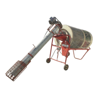
Photo 52 shows a Model 40 Hi-Cap Grain Cleaner with optional trash pan attach-
ment, less auger.
Photo 53 shows a Model 40 Hi-Cap Grain Cleaner with optional trash pan, and 4’
x 15’ Trash Auger.
MODEL 40 8” x 8’ FEED-IN AUGER
Assembly Instructions
Component Parts for 8’ Feed-In Auger
Step 1 Place sealed bearing between bearing flanges, and bolt to auger head. BE
SURE eccentric lock is on the outside. Use two 5/16” x ¾” carriage bolts, lock
washers and nuts. See Photos 1 and 2.
Step 2 Slide stub shaft into upper end of auger flighting. BE SURE keyway is left ex-
posed. Fasten with two 3/8” x 1-3/4” Grade 5 bolts, and 3/8” lock nuts. See Photos
3 and 4.
Step 3 Place auger head over auger tube, sliding stub shaft through bearing. See Photo
5.
Step 4 Install 1” locking collar onto bearing. BE SRUE to lock the collar with the rotation
of the shaft. Auger shaft should stick through the locking collar 1-5/8”. Securely
tighten locking collar set screw. See Photos 6,7 and 8.
Step 5 Using one 2” strap bracket, four 3/8” x 1-
1
/4
” bolts and nuts, fasten auger head
securely to auger tube. See Photos 9 and 10.
Step 6 Place a ½” nut on the threaded stub bolt on the auger head. Slide motor mount
angle over stub bolt and thread another ½” nut over the angle. Install motor mount
base plate to the auger head, using two 3/8” x ¾” carriage bolts, lock washers and
nuts. Do NOT tighten at this time. See Photos 11 and 12.
Step 7 Put two 5/16” x ¾” carriage bolts, lock washes and nuts through motor mount
angel, and motor mount base plate.
Assembly Instructions (continued)
 Loading...