6
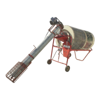
Assembly Hi-Cap 40 Grain Cleaner
For 2 HP motor, bolt as in Photo 13.
For 1-
1
/
2
HP motor, bolt as in Photo 14.
Step 8 Using 5/16” carriage bolt, lock washer and nut, bolt the rear of the motor mount
base plate to the rear support on the auger head. See Photo 15.
Step 9 Bolt the auger pivot pin to under side of the auger head, using ½” x 3-
1
/
2
” bolt and
lock nut. Auger pivot must have free movement. See Photo 16.
Step 10 Install ¼” key into auger shaft. Then put 12” pulley onto shaft, hub first. Make shaft
flush with the outer edge of the pulley. Tighten setscrews. See Photos 17, 18 and
19.
Step 11 Bolt the motor to the motor mount base plate, using four 5/16” x 1” bolts, two flat
washers, one look washer per bolt and nuts. See Photo 20.
Step 12 Put key and 3” pulley to the motor shaft; align motor pulley with 12” auger pulley and
install belt. Adjust belt tension by raising the ½” nuts on the threaded stub bolts.
After belt adjustment has been made, tighten all bolts left loose during motor mount
assembly. See Photos 21 and 22.
Auger motor must be wired the same voltage as cleaner and checked for proper
rotation.
Step 13 Using two 5/16” carriage bolts, lock washers and nuts, bolt the belt shield to the
tabs on the auger head. See Photo 23.
Step 14 Put wooden bearing between bearing flanges and bolt to tail cage hopper with
three 3/8” x ¾” carriage bolts, flat washes, lock washers and nuts. See Photos 24
and 25.
Step 15 Install hopper wheel bracket, using two 3/8” x ¾” carriage bolts, flat washers, lock
washers and nuts. Slide two 5/8” SAE washers onto the shaft, then the wheel, and
another 5/8” SAE washer. Finish by installing a 1-
1
/
4
” cotter pin. See Photos 26 and
27.
Step 16 Slide flow restrictor tube into intake end of auger tube with nut welded onto
restrictor tube on the outer end. See Photo 28.
Step 17 Put the tail cage hopper assembly onto the auger tube. Insert the end of auger
shaft into the wooden bearing. Secure the tail cage hopper assembly to the auger
tube by using two 2” strap brackets. (Be sure to put the 2” strap bracket with pipe
and threaded nut toward the top of the tail cage assembly as shown in Photo 29
and 30.) Securely fasten with four 3/8” x 1-
1
/
4
” hex head bolts as shown in Photo 31.
Assembly Instructions (continued)
 Loading...