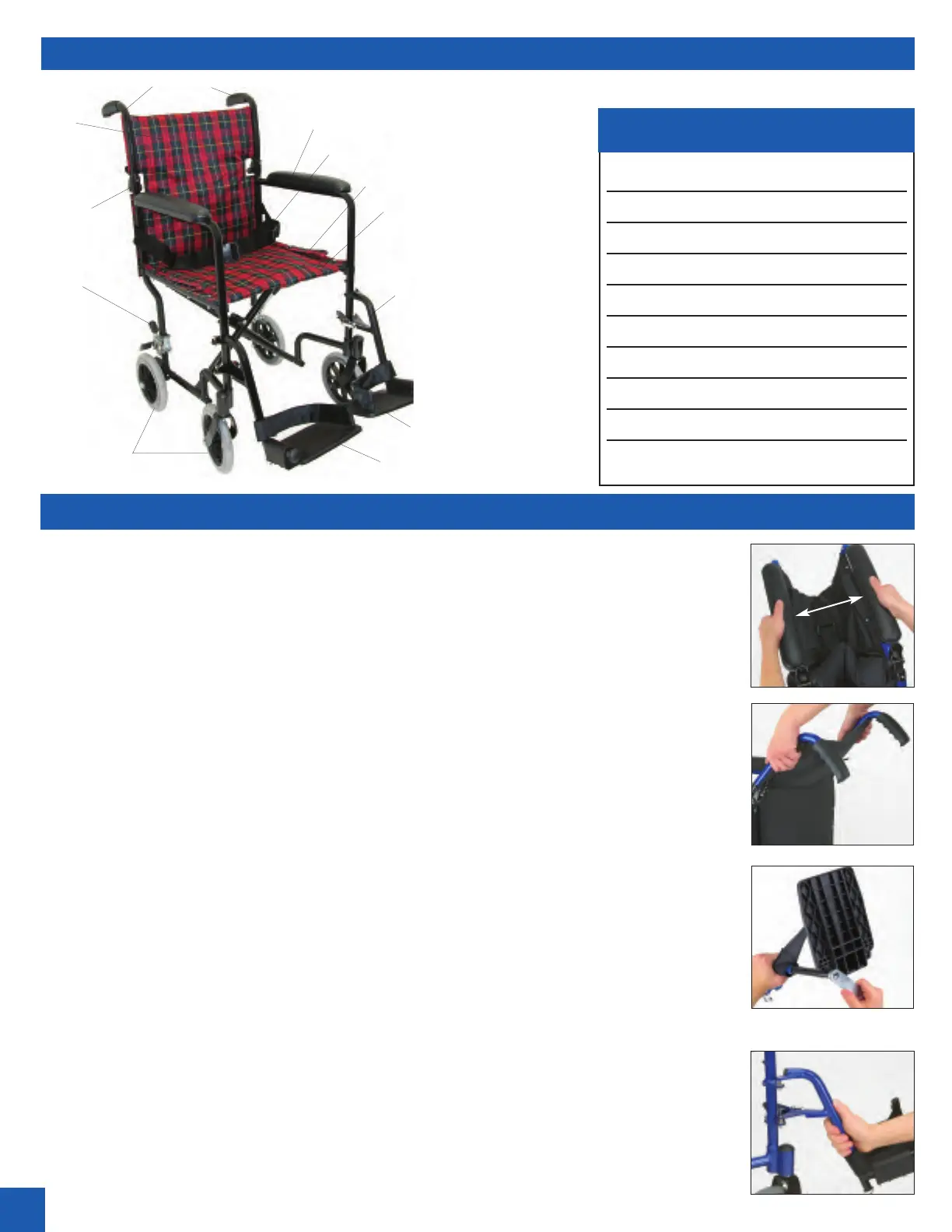
Overall Width: 23”
Overall Length (with footrests): 33”
Wheels: 8”
Handle Height: 38”
Armrest Height: 29”
Width Between Armrests: 16-1/2”
Seat: 19” x 16”
Seat Height: 19”
Approximate Weight: 20 lbs.
Weight Capacity: 250 lbs.
Assembly Instructions:
1. Firmly grasp the padded armrests and pull the armrests apart to unfold chair,
Fig. 1.
2. Flip up the backrest,
Fig. 2, and push the top of the backrest toward the chair
until the brass pins snap into the openings on the frame.
3. Using the included tool, adjust the length of the footrests by loosening the hex-
nut on the base of the footrest,
Fig. 3. Separate the tubing from the frame and
adjust to the desired length. Tighten the hex-nut with the included tool.
4. Align the holes on the footrest frame with the posts on the crescent-shaped
brackets above the front wheels of the chair,
Fig. 4. NOTE: The post that anchors
the nylon foot strap to the footrest should always face toward the inside of the
transport chair. Twist the footrest toward the center of the chair until the silver
hinge connects with the frame. Repeat for remaining footrest.
5. Flip up footrests before patient sits in chair. Fasten the seatbelt and flip down
footrests. Position patient’s feet in front of nylon straps.
WARNING! It is very important that you read all instructions before assembly
and/or use of this transport chair. Before using the transport chair, be sure the
patient’s weight is within the weight capacity of the unit. This transport chair will
require little assembly, which can be performed with the included tool.
Parts for Assembly:
Transport chair; two adjustable footrests; one tool for assembly
INSTRUCTIONS FOR ASSEMBLY
PARTS OF TRANSPORT CHAIR AND SPECIFICATIONS
Handles
8” wheels
S
eat
b
ack
F
olding
hinge
Brake
lever
Folding handle
Nylon strap
Seat
Swing-away leg rigging
P
added armrest
Seatbelt
2
SPECIFICATIONS
1052-Series
Fig. 1
Fig. 2
Fig. 3
Fig. 4
Footrest