Do you have a question about the DoAll c-530 nc and is the answer not in the manual?
Explains the purpose of the manual to guide safe operation using texts, drawings, and diagrams.
Manual written to comply with European Machine Directive UNI-EN 89/392 and related standards for safe machine use.
Outlines the information contained in the document, covering installation, use, maintenance, servicing, and dismantling.
Provides identification details of the Band Saw machine, including serial number, year, voltage, and power unit specifications.
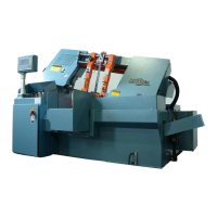
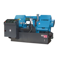
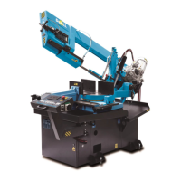
Details the machine's primary construction features, including control systems, motors, vises, and frame materials.
Explains blade speed control, the working surface design, and the indexing system for material feeding and positioning.
Describes the hydraulic vises used for clamping, noting the tempered inserts and pressure reducer valve for protection.
Guides users on understanding the manual's structure, audience, and update policy for effective use.
Details conditions under which the manufacturer is not responsible for machine use, including inappropriate operations.
Specifies professional use requirements, operator qualifications, applicable regulations, and typical machine applications.
Explains manual and automatic control modes, stop functions, and emergency stop procedures for machine operation.
Details procedures for taking the machine out of service and general safety precautions related to power and operation.
Lists main structural components like base frame, cutting bridge, hydraulic power unit, control panel, and coolant system.
Describes the cutting bridge frame, guiding columns, and their connections, including vise system overview.
Details the lifting cylinder, blade tension assembly, band drive, band guides, and servo-control mechanisms.
Explains the hydraulic power unit components and the electrical system, including control console and enclosure.
Describes the machine's protection measures, including areas that cannot be fully covered and warning stickers.
Provides guidance on safely moving the machine and outlines the installation process, emphasizing safety during lifting.
Details site preparation, electrical connection, and pre-power checks required before operating the machine.
Lists limit switches, signaling devices, fixed protections, and moveable protections that ensure machine safety.
Introduces the SAW 3 control system, its functions, and the procedure for switching the machine ON.
Explains machine status icons, manual cycle operations, and the function key layout for machine control.
Details material handling, semi-automatic and automatic cycles, including program directory access.
Guides users on creating new cutting programs and lists for automated operation.
Covers running, modifying programs, selecting coolant types, and general parameter setup.
Details various parameter setup menus, including axis, hydraulic, and vise parameters.
Explains language selection, testing, software updates, PC connections, and advanced parameter settings.
Details help function, head feed control, feed system selection, automatic workstop, and band deviation monitor.
States that only expert personnel should perform the dismantling of the machine.
Lists common operational problems, their causes, and solutions for issues related to the base, chip conveyor, and cutting bridge.
Provides a detailed lubrication schedule for various machine components, specifying lubricant types and maintenance frequencies.
Lists common operational problems and their solutions, along with procedures for safely replacing the saw blade.
Addresses dangers associated with electrical power, emphasizing safety rules during servicing and customer responsibility for power source.
Discusses training requirements for operators and maintenance personnel, highlighting experience and schematic understanding.
Identifies the tested machine and lists the norms it complied with, indicating positive test results.
States that electrical and hydraulic schematics are provided on the following pages.
| Voltage | 230/460V |
|---|---|
| Frequency | 60 Hz |
| Blade Size | 1 x 0.035 in |
| Blade Width | 1 in |
| Blade Thickness | 0.035 in |