Do you have a question about the DoAll DS-320SA and is the answer not in the manual?
Describes the step-by-step process of operating the machine's cutting cycle.
Details the PLC control system, its features, and operator settings.
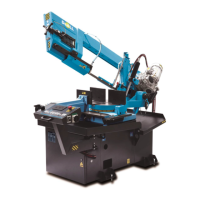
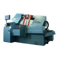
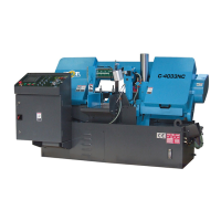
Explains the physical design and components of the machine.
Lists the standard components and features included with the machine.
Lists essential basic equipment provided with the machine.
Defines the intended use and applications of the sawing machine.
Details the specific tools provided for common machine maintenance and service.
Provides specifications for various cutting parameters based on material and angle.
Lists the physical dimensions of the machine relevant for transportation.
Details the specifications of the machine's drive components.
Specifies the types and quantities of oils and fluids required for operation.
Reports on machine noise levels during operation.
Describes the information contained on the machine's production label.
Explains the vice mechanism, its adjustment, and operation.
Describes the machine's arm, including its components and movements.
Details the hydraulic unit, its components, and functions.
Provides essential safety guidelines for operating the machine.
Identifies potential mechanical and electrical hazards associated with the machine.
Outlines fire safety precautions and requirements for the machine's environment.
Covers safety aspects and requirements for the machine's electrical components.
Lists actions that are strictly forbidden during machine operation or maintenance.
Details general safety regulations and operational warnings for the machine.
Instructs on checking the machine for any damage incurred during shipping.
Details the removal of shipping brackets before machine setup.
Details the overall process of installing the machine.
Explains how to correctly level and install roller tables with the machine.
Details the process of anchoring the machine to the floor using mechanical anchors or threaded rods.
Guides on connecting the machine to the electrical power supply safely.
Explains the function of each button on the machine's keypad interface.
Details the Human-Machine Interface panel and its interactive elements.
Describes the elements and information displayed on the initial HMI screen.
Details the different menu options accessible via the HMI panel.
Explains the layout and function of the numeric keypad used for input.
Lists and describes user-adjustable parameters for machine settings.
Describes the manual control interface for saw operations, used in specific situations.
Outlines essential steps to perform before starting any cutting operation.
Guides on bringing the machine to an operational ready state.
Provides instructions for setting linear and miter angles for cuts.
Explains the procedure for setting up and performing right-angle cuts.
Describes the process for setting up and performing left-angle cuts.
Explains the function of the digital angle indicator, an optional accessory.
Details how to adjust the machine's upper and lower working positions.
Details how to set the automatic end stop for the upper working position.
Explains how to adjust the machine's down working position.
Provides instructions on correctly adjusting the vice for secure material clamping.
Guides on positioning the saw band guides for optimal cutting quality.
Explains the lubrication system for the saw band and its components.
Details the procedure for setting the adjustable end stop for material positioning.
Provides guidance on safely handling materials before and after cutting.
Lists the prerequisites and conditions for performing a cutting operation.
Describes how to power on the hydraulic unit for operation.
Outlines the step-by-step process for executing a cut using the semiautomatic cycle.
Explains how system errors are displayed and how to interpret them.
Explains how to properly tension the saw band for optimal performance.
Provides instructions for safely replacing the saw band.
Describes the function and adjustment of the saw blade guides.
Details the specific steps for changing a worn-out cleaning brush.
Discusses the types of saw blade teeth (constant vs. variable) and their impact.
Provides tables and guidance for selecting the correct teeth per inch for cutting.
Explains the necessary break-in procedure for new saw blades.
Illustrates methods for clamping material to ensure cutting precision and blade life.
Uses chip analysis to guide setting the optimal arm movement speed during cutting.
Guides on setting up and adjusting the mini-lube system for lubrication.
Explains the control switch for the mini-lube system's lubrication modes.
Details how to set the upper thrust based on material diameter and jaw composition.
Lists routine daily maintenance tasks for the machine.
Outlines essential weekly maintenance checks and procedures.
Details how to check and perform lubrication on various machine parts.
Lists technical maintenance intervals for the gearboxes.
Explains how to adjust the band guides for optimal cutting accuracy and band life.
Details the process of adjusting clearance between the saw band and carbide pads.
Provides guidance on adjusting the tensioning pulley assembly for proper band tension.
| Blade Length | 128 inches |
|---|---|
| Blade Width | 1 inch |
| Motor Power | 3 HP |
| Coolant Pump Motor | 1/8 HP |
| Table Size | 15 x 15 inches |
| Table Height | 36 inches |
| Weight | 650 lbs |
| Type | Semi-Automatic Horizontal Bandsaw |
| Cutting Capacity (Round) | 12.6 inches |
| Blade Thickness | 0.042 inches |