DS-320SA
Instruction Manual - 47 -
www.doallsaws.com
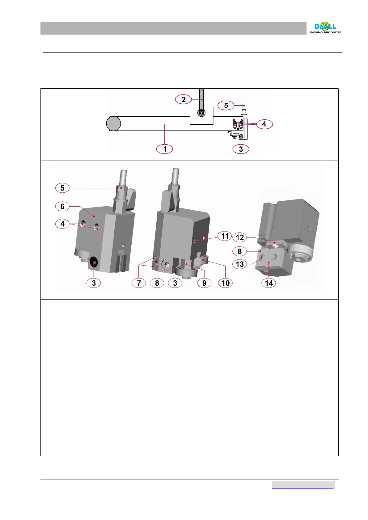
11.3 GUIDES OF THE BLADE
The guides direct the band into a precision cut. Each band guide has four replaceable carbide pads that are
constantly awash with coolant during the cutting process. The guides are factory pre-set. If new adjustment
is necessary, we recommend ordering maintenance service of the DOALL company.
When cutting, try to adjust the front adjustable guide as close to the sawn material as possible.
pic: 11-2
pic: 11-3
1. Adjustable guide console.
2. Fixation screw of the guide console.
3. Tightening screw of the movable distance piece with the leading carbide desks.
4. Tightening screws of the guide – do not manipulate, as this affects the life of the blade.
5. Valve regulating the amount of coolant.
6. Body of the guide.
7. The adjusting screws of the movable distance piece with the leading carbide desks. When setting the
right position, tighten the tightening screws, by tightening of the adjustable screws set the clearance
between the leading desks to the value 0,037 in, ( the clearance between the blade and leading
desks), check the tightening of the tighening screws and clearances. We recommend to check the
clearance. We recommend to have the spare guide desks on stock. We recommend to have the
adjusting of the clearance of guide desks done by a service technician from – company.
8. Leading carbide desks.
9. Hexagon of the cam. When replacing the band, rotate the cam so that the clearance between the
slack band and the bearings is as small as possible. This will make replacement possible.
10. The leading bearings are situated on excenter. It is possible to adjust the position of bearings as close
the blade as possible but with the assembling clearance. We recommend to have spare bearings on
stock.
11. Holes for attaching a band guard.
12. Leading carbide desks. If a notch is carved by the band’s flank (deeper than 0.012 mm), replace it.
13. Tightening screw of the leading carbide desks.
14. The movable distance piece.