EasyManua.ls Logo

DoAll 2613-V3 - User Manual

DoAll 2613-V3
28 pages
Print Icon
To Next Page IconTo Next Page
Loading...
2613-V3
Serial No: 589-09101 to
Band Sawing Machine
Instruction and Parts Manual
Question and Answer IconNeed help?

Do you have a question about the DoAll 2613-V3 and is the answer not in the manual?

Summary

DAMAGE CLAIM PROCEDURES

VISIBLE DAMAGE AT THE TIME OF DELIVERY

Procedures for handling visible damage upon delivery of the machine.

CONCEALED DAMAGE

Procedures for handling damage discovered after delivery.

MACHINE DIMENSIONS

FLOOR PLAN

Diagram showing the machine's footprint and overall dimensions.

FRONT VIEW

Illustrates the machine's front profile, including key dimensions.

MACHINE FEATURES

FRONT VIEW

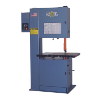
Identifies and labels key components of the band saw from the front.

INSTALLATION

LOCATION

Guidelines for selecting an appropriate placement for the machine.

OSHA NOTICE!

Safety regulation regarding anchoring the machine.

UNPACKING

Steps for safely removing the machine from its shipping container.

CLEANING

Instructions for removing protective coatings before operation.

LIFTING

Procedures and weight information for safely lifting the machine.

MACHINE INSTALLATION and ALIGNMENT

Steps for leveling and aligning the machine on its base.

MACHINE INSTALLATION and ALIGNMENT

Detailed steps for squaring the worktable and ensuring proper alignment.

ELECTRICAL INSTALLATION

ELECTRICAL INSTALLATION

Guidelines for connecting the machine to the electrical power supply.

PREPARATION FOR USE

PREPARATION FOR USE

Procedures for checking oil levels and air supply before initial operation.

OPERATION

SAFETY PRECAUTIONS

Critical safety rules for operating the band saw machine.

USING THE JOB SELECTOR

How to use the Job Selector chart for material and cutting parameters.

ELECTRICAL CONTROLS

Other Controls

Explains the function of the disconnect switch and worklight.

BAND SPEED CONTROLS

Details on adjusting band speed and shifting gears.

SAW BAND PREPARATION

Saw Band Selection

Information on choosing the correct saw band width and type.

Insert-Type Saw Guide Adjustment

Steps for adjusting insert-type saw guide blocks for proper fit.

Saw Band Removal

Procedures for safely removing a saw band from the machine.

Saw Band Installation

Steps for installing a new saw band onto the bandwheels.

Saw Band Tension Adjustment

How to properly tension the saw band using the adjustment knob.

Saw Band Tracking

How to adjust bandwheel tilt for correct saw band tracking.

POST ADJUSTMENT

POST ADJUSTMENT

How to adjust the post and upper saw guide elevation.

WORKTABLE AND TILT ADJUSTMENT

WORKTABLE AND TILT ADJUSTMENT

Information on the standard worktable size and tilt adjustment.

WORKTABLE AND TILT ADJUSTMENT

Details on worktable tilt adjustment and accessory mounting.

WHEEL BRUSH AND CHIP REMOVAL

WHEEL BRUSH AND CHIP REMOVAL

How to use and maintain the wheel brush for chip removal.

TYPICAL SAWING PROCEDURES

TYPICAL SAWING PROCEDURES

General steps for setting up and performing sawing operations.

Contour Sawing

Specific procedures and precautions for contour sawing.

TYPICAL SAWING PROCEDURES

Advice on preventing band twisting and recording settings.

Internal Contours

Steps for preparing and performing internal contour sawing.

LUBRICATION

LUBRICATION CHART

A table detailing lubrication points, intervals, and recommended lubricants.

LUBRICATION DIAGRAM

Visual representation of lubrication points on the machine.

MAINTENANCE

REPLACING BANDWHEEL TIRES

Step-by-step guide for removing and replacing bandwheel tires.

INSERT-TYPE SAW GUIDES

Information on the roller back-up bearing for insert-type guides.

ELECTRIC MOTORS

Instructions to follow manufacturer's maintenance for electric motors.

HEAD COMPONENTS

Procedure for occasional oiling of the post and slide block.

TRANSMISSION

Procedures for draining, flushing, and refilling the transmission.

WHEEL BRUSH

How to check and adjust the lower bandwheel brush.

MACHINE CLEANING

Guidelines for cleaning the machine and its parts.

MACHINE CLEANING

Instructions for removing chip pans and general cleaning.

BAND DRIVE BELT

BAND DRIVE BELT

How to adjust and replace the band drive belt.

MIST COOLANT

MIST COOLANT

Information on air leaks, clogging, and maintaining mist coolant system.

BAND MIST LUBRICATOR

BAND MIST LUBRICATOR

Guidance on operating and adjusting the band mist lubricator.

TROUBLE SHOOTING

MACHINE WONT START

Troubleshooting steps for when the machine fails to start.

MACHINE VIBRATION

Potential causes and solutions for machine vibration.

SAW BAND VIBRATION

Troubleshooting steps for saw band vibration issues.

SAW BAND IS CUTTING INACCURATELY

Reasons and fixes for the saw band cutting inaccurately.

EXCESSIVE INSERT AND BLADE WEAR

Causes and solutions for excessive wear on inserts and blades.

PREMATURE BLADE TEETH DULLING

Factors contributing to premature dulling of blade teeth.

TROUBLE SHOOTING

Troubleshooting for faulty material and saw band vibration.

TRANSMISSION WILL NOT STAY IN GEAR

Diagnosing and fixing issues with the transmission staying in gear.

TRANSMISSION WILL NOT SHIFT INTO GEAR

Troubleshooting steps for transmission shifting problems.

SAW BAND SLIPS OFF BANDWHEEL

Causes and solutions for the saw band slipping off the bandwheel.

SURFACE FINISH ON WORK IS TOO ROUGH

Addressing issues causing a rough surface finish on cut work.

NO COOLANT FLOW (If Supplied)

Troubleshooting steps for no coolant flow from the system.

ACCESSORIES

DISC CUTTER

Instructions for setting up and using the disc cutter accessory.

RIP FENCE

Steps for installing and using the rip fence fixture.

HEAVY WORK SLIDES

Information on using heavy work slides for supporting stock.

HEAVY WORK SLIDES

Details on replacing the center plate when using heavy work slides.

WORKHOLDING JAWS

WORKHOLDING JAWS

How to use workholding jaws for off-hand and contour sawing.

AIR-OPERATED POWER FEED

AIR-OPERATED POWER FEED

Requirements and operation of the air-operated power feed attachment.

CHIP BLOWER

CHIP BLOWER

How to use the chip blower to clear chips from the sawing area.

MAGNIFIER

MAGNIFIER

Using a magnifier to aid in delicate sawing procedures.

POST ELEVATING HANDWHEEL

POST ELEVATING HANDWHEEL

Adjusting the post and upper saw guide using the handwheel.

WORKTABLE OPTIONS

Auxiliary Table

Information on the auxiliary table for supporting heavy workpieces.

18 Stroke Worktable

Details on the factory-installed air-powered worktable with an 18-inch stroke.

Glide Table

Features and operation of the glide table worktable option.

WORKTABLE OPTIONS

Features of the worktable like work rest pins and squaring bars.

HMD Hydraulic Table

HMD Hydraulic Table

Information on the factory-installed hydraulic-powered worktable.

AIR-POWERED WORKTABLE

AIR-POWERED WORKTABLE

How this attachment reduces work height capacity.

Production Sawing

Set-Up

Procedures for positioning workstops and tilting the worktable.

Production Sawing

Steps for setting up stock and controlling feed force for production sawing.

DBW-15 BUTTWELDER

DBW-15 BUTTWELDER

Reference to manual for blade welding and buttwelder operation.

OPTIONAL SAW GUIDE BLOCKS

OPTIONAL SAW GUIDE BLOCKS

Options for equipping the machine with precision saw guides.

Insert-Type Saw Guides

Details on high speed and precision insert-type saw guides.

Roller Saw Guides

Information on type I and type II roller saw guides for high-speed sawing.

OPTIONAL SAW GUIDE BLOCKS

How type II roller guides affect work height and table tilt.

90° SAW GUIDE BRACKETS

90° SAW GUIDE BRACKETS

Use of brackets to cut materials longer than throat capacity.

ADJUSTABLE ANGLE SAW GUIDES

ADJUSTABLE ANGLE SAW GUIDES

How to adjust guides for 45° and 90° band angles.

DUST SPOUT

DUST SPOUT

Location and purpose of the dust spout for chip collection.

MATERIAL HANDLING EQUIPMENT

MATERIAL HANDLING EQUIPMENT

Information on special equipment to enhance machine performance.

Overview

This document is an Instruction and Parts Manual for a DoALL 2613-V3 Band Sawing Machine. It provides comprehensive information on the machine's dimensions, features, installation, operation, maintenance, troubleshooting, and available accessories.

Function Description

The DoALL 2613-V3 is a metal-cutting band saw designed for various sawing operations, including production sawing, contour sawing, and internal contour sawing. It uses a continuous saw band to cut materials, offering versatility for different shapes and sizes. The machine is equipped with features to control band speed, tension, and worktable tilt, allowing for precise and efficient cutting.

Important Technical Specifications

  • Model: 2613-V3
  • First Serial No.: 589-09101
  • Machine Dimensions (Floor Plan):
    • Width: Approximately 59.50 inches (1511.3 mm)
    • Length: Approximately 44.50 inches (1130.3 mm)
    • Height: Approximately 84.50 inches (2146.3 mm)
    • Worktable: 26 x 26 inches (660.4 x 660.4 mm)
  • Work Height Options (Dimension B - overall height):
    • 13" (330.2 mm) work height: 84.64" (2149.9 mm) overall height
    • 18" (457.2 mm) work height: 90.64" (2302.3 mm) overall height
    • 24" (609.6 mm) work height: 96.64" (2454.7 mm) overall height
    • 30" (762.0 mm) work height: 102.64" (2607.1 mm) overall height
  • Throat Depth: 26.03 inches (661.2 mm)
  • Saw Band Length: 183 inches (4648.2 mm)
  • Saw Band Widths: 1/16 to 1 inch (1.5 to 25.4 mm)
  • Band Speed Ranges:
    • LOW: 30 to 320 fpm (10 to 100 m/min)
    • HIGH: 550 to 5500 fpm (170 to 1675 m/min)
  • Worktable Load Capacity: 500 pounds (226.8 kg) evenly distributed (no impact)
  • Worktable Tilt: Up to 10° left and 45° right
  • Air Supply (for optional accessories): 80 to 90 psi (5.5 to 6.2 bar or 5.6 to 6.3 kg/cm²), not to exceed 90 psi.
  • Transmission Oil Capacity: 1 quart (0.95 liters)
  • Mist Coolant Reservoir (Optional) Capacity: 1 quart (0.47 liters)
  • Band Mist Lubricator (Optional) Capacity: 16 ounces (0.95 liters)

Usage Features

  • Job Selector: A chart located on the upper bandwheel door provides recommended band type, pitch, speeds, and cutting rates based on material type and thickness. It also includes a radius guide for minimum radii cuts.
  • Electrical Controls: Located on the side of the electrical control box for operator convenience, including Band Speed knob, Band Start button, and Emergency Stop button.
  • Band Speed Controls: A transmission gear shift lever allows selection between "HIGH" and "LOW" band speed ranges. The Band Speed knob adjusts variable speed within each range.
  • Saw Band Preparation: Instructions for selecting the correct saw band, adjusting insert-type saw guides, and installing/removing saw bands. Saw band tension is adjusted via a knob below the sawing head, with a scale indicating recommended tensions.
  • Saw Band Tracking: The upper bandwheel can be tilted to ensure correct saw band tracking, where the band center follows the center of both crowned rubber bandwheel tires.
  • Post Adjustment: The post and upper saw guide elevation can be adjusted to accommodate workpieces up to 13 inches (330.2 mm) high (or more with extra work height options).
  • Worktable and Tilt Adjustment: The worktable can be tilted for compound angles, with a pointer and calibrated scale indicating the tilt angle.
  • Typical Sawing Procedures: Detailed steps for machine setup, including raising the post, tilting the worktable, loading stock, determining band speed, and beginning the cut.
  • Contour Sawing: Specific precautions for contour sawing, such as reducing feed force when cutting into an opening and using appropriate saw band widths for curves.
  • Internal Contours: Procedures for internal contour sawing, involving drilling a starting hole, running the saw band through, and welding the band.
  • Accessories: A range of optional accessories are available, including a Disc Cutter for circular cuts, Miter No. 2 Cut-Off for angled cuts, Rip Fence for straight cuts, Heavy Work Slides for large workpieces, Workholding Jaws for contour sawing, Air-Operated Power Feed for steady feeding pressure, Chip Blower, Mist Coolant, Band Mist Lubricator, Worklight, Magnifier, Post Elevating Handwheel, Auxiliary Table, 18" Stroke Worktable, Glide Table, DBW-15 Buttwelder, Optional Saw Guide Blocks (high-speed, precision, roller, steel/carbide-faced), 90° Saw Guide Brackets for increased throat capacity, Adjustable Angle Saw Guides for angled cuts, Dust Spout, and Material Handling Equipment.

Maintenance Features

  • Damage Claim Procedures: Detailed instructions for handling visible and concealed damage claims upon delivery, including reporting, inspection, documentation, and filing claims.
  • Lubrication Chart and Diagram: Provides a comprehensive guide to lubrication points, recommended lubricants, and lubrication intervals for various machine components (e.g., band tension screw, post, bandwheel slide, transmission, electric motor, mist coolant reservoir, band mist lubricator).
  • Replacing Bandwheel Tires: Step-by-step instructions for replacing worn bandwheel tires, including removal of old tires, cleaning, application of primer and adhesive, and seating new tires.
  • Transmission Maintenance: Recommendations for yearly draining, flushing, and refilling of transmission oil, checking for seal leaks, investigating unusual noises, and returning faulty transmissions for repair.
  • Wheel Brush: Regular checking and adjustment of the lower bandwheel brush to ensure it just touches the bandwheel tire, and replacement when necessary.
  • Machine Cleaning: Instructions for periodic removal of chips and debris from various machine areas, including the chip pan, saw guides, worktable, T-slots, bandwheels, and slides.
  • Band Drive Belt: Procedures for adjusting tension and replacing the band drive belt.
  • Mist Coolant and Band Mist Lubricator: Maintenance instructions for checking for air leaks, preventing clogging, cleaning applicator nozzles and filters, and following manufacturer's guidelines for lubricator maintenance.
  • Insert-Type Saw Guides: Instructions for replacing roller back-up bearings.
  • Electric Motors: Advises following manufacturer's maintenance instructions.
  • Head Components: Regular oiling of the post and moving it through the slide block.
  • Troubleshooting Guide: A detailed section addressing common issues such as the machine not starting, machine vibration, saw band vibration, inaccurate cutting, excessive insert and blade wear, premature blade teeth dulling, transmission issues, saw band slipping, and poor surface finish.

DoAll 2613-V3 Specifications

General IconGeneral
BrandDoAll
Model2613-V3
CategorySaw
LanguageEnglish

Related product manuals